Industrial motors are the heartbeat of your facility. When one fails unexpectedly, the consequences ripple outward — production stalls, safety risks escalate, and repair costs skyrocket. Yet most maintenance teams are still reacting to failures rather than anticipating them. Without a structured predictive maintenance program for industrial motors, every shift starts with uncertainty. This guide walks you through a proven, step-by-step framework to move from reactive chaos to data-driven confidence — protecting your motors, your uptime, and your bottom line.
A predictive maintenance (PdM) program uses real-time and periodic diagnostic data to predict when a motor is likely to fail — long before it actually does. Unlike scheduled preventive maintenance (which replaces components on fixed intervals regardless of condition), PdM intervenes only when data signals that intervention is needed.
A well-designed PdM program for industrial motors typically incorporates:
The result is a motor fleet that is continuously monitored, faults are caught weeks or months in advance, and maintenance resources are deployed where they are genuinely needed.
Unplanned motor failures cost significantly more than preventive or predictive interventions — not just in replacement parts, but in:
Understanding motor winding failure signs before they cause a catastrophic breakdown is one of the most direct ways to eliminate these hidden costs. Insulation degradation, turn-to-turn shorts, and partial discharge events are all detectable well in advance — if you have the right tools and a systematic testing cadence in place.

Before purchasing a single piece of diagnostic equipment, start with a complete inventory and criticality ranking of every motor in your facility.
For each motor, document:
Assign a criticality score based on factors such as replacement lead time, impact on production if it fails, and safety implications. Motors that are on the critical path and difficult to replace quickly should receive the most frequent monitoring and the most comprehensive diagnostic testing.
This inventory becomes the master reference for every downstream decision in your predictive maintenance program for industrial motors — from how often to test, to which tools to use, to what action thresholds to set.
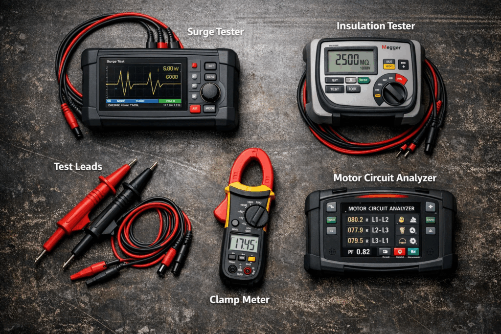
The diagnostic tool stack you choose determines the quality of your fault detection. No single test covers every failure mode. A robust PdM program layers multiple complementary techniques.
Motor Circuit Analysis is a de-energised test method that evaluates the electrical condition of a motor’s windings, rotor, and insulation system without needing to run the motor. It measures impedance, inductance, resistance, and capacitance across phases to identify imbalances that signal developing faults.
MCA is an ideal first-line diagnostic for motors before they are reinstalled after rewinding, or as a periodic health check for motors that cannot be taken offline easily.
Electrical Signature Analysis is performed on motors while they are running under load. By analysing the current and voltage waveform signatures, ESA can detect rotor bar defects, air gap eccentricity, bearing wear, and developing insulation issues — all without physical contact with the motor.
ESA is particularly powerful for motors that are difficult to access for mechanical inspection, such as submersible pumps or enclosed production line drives.
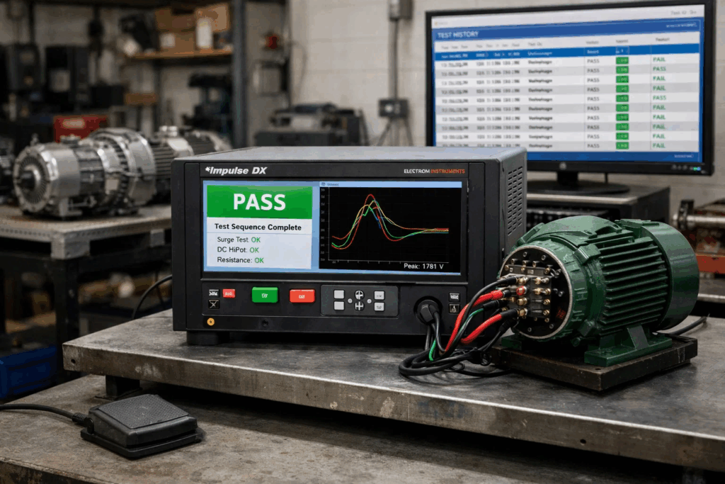
Surge testing subjects motor windings to controlled high-voltage pulses and compares the resulting waveform responses between phases. Any deviation — measured through the Error Area Ratio (EAR) — reveals turn-to-turn insulation weakness before it becomes a full winding failure.
Understanding what the Error Area Ratio means in surge testing is critical for setting accurate pass/fail thresholds. An EAR value above an acceptable limit is a direct, quantifiable indicator that a motor’s insulation is compromised and requires intervention.
For a deeper understanding of the technology, what is a surge tester is a helpful primer on how the equipment works and what faults it targets. Knowing the difference between a megger test and a surge test for windings will also help you select the right test for each failure mode.
When building your testing workflow, you should also evaluate whether manual or automatic surge testing better suits your environment. High-volume motor repair shops and production line testing typically benefit significantly from automation.
Tip: When testing high-voltage motors (above 10kV), waveform analysis in surge testing provides additional diagnostic depth by revealing partial discharge events embedded within the surge waveform.
The megger test is one of the oldest and most widely trusted tools in a motor maintenance programme. It applies a DC voltage to the winding-to-earth circuit and measures the resulting insulation resistance in megaohms. A declining trend in insulation resistance over successive tests is one of the earliest warning signs of moisture ingress, contamination, or thermal degradation.
Read the detailed guide on how to perform a megger test to understand test voltages by motor class, acceptable resistance values, and the Polarisation Index (PI) method for deeper insulation assessment.
For motors operating above 3.3kV, partial discharge (PD) testing is an essential addition to the PdM toolkit. PD events are small electrical discharges within voids or cracks in the insulation that erode winding insulation over time. Left undetected, PD damage is progressive and typically leads to catastrophic winding failure.
HiPot (high potential) testing verifies the dielectric integrity of a motor’s insulation by applying a voltage significantly above the motor’s rated voltage. The difference between AC HiPot and DC HiPot testing is important to understand — each method has distinct advantages depending on the insulation type, motor voltage class, and whether you are conducting proof testing or routine monitoring.
For motors where surge testing and HiPot are needed in a single instrument, understanding HiPot functionality within a digital surge tester explains how combined testers streamline your workflow.

Predictive maintenance is fundamentally about trend analysis. A single data point tells you the current state of a motor. A series of data points over time tells you whether the motor is degrading, stable, or improving.
When a new motor is commissioned — or a rewound motor is returned from the repair shop — perform a full diagnostic suite and record the results as your baseline. This baseline becomes the reference against which all future tests are compared.
Baseline tests should include:
For motors where checking the windings on a 3-phase motor is part of the routine, the baseline also includes phase-to-phase resistance balance percentages. A shift of more than 5% from baseline is typically considered a warning threshold in most industry standards.
Not every motor needs the same testing frequency. The monitoring cadence should be proportional to the motor’s criticality score, its operating environment, and its age.
| Motor Category | Recommended Monitoring Interval |
|---|---|
| Critical (production-stopping, high kW) | Monthly or quarterly |
| Important (moderate impact on production) | Every 6 months |
| Non-critical (easily replaced, low kW) | Annually |
| Post-rewind or post-repair | Immediately at reinstatement |
| Before critical operational period | 2–4 weeks prior |
Motors that show early signs of winding insulation failure should be moved to a shorter monitoring interval immediately, regardless of their standard schedule.
Manual testing is time-consuming, subject to operator variation, and difficult to sustain consistently across large motor fleets. Automated motor testing systems dramatically improve throughput, reduce human error, and enable consistent test parameter application across every motor tested.
Key automation advantages include:
For facilities with surge testers, using a footswitch for hands-free surge testing is a practical safety enhancement that improves both operator safety and testing consistency.
One of the most underutilised assets in a mature predictive maintenance program for industrial motors is historical failure data. Every motor failure — whether anticipated or not — should be documented with:
Over time, this database allows you to refine your alert thresholds, prioritise test types for specific motor models or environments, and build predictive models based on your own plant’s failure history. It transforms your PdM program from a generic framework into a plant-specific intelligence system.
Regularly reviewing troubleshooting electrical testing errors as part of your team’s ongoing training ensures that the test data entering your database is accurate and actionable.
A credible predictive maintenance program for industrial motors must operate within recognised standards. This ensures test procedures are valid, equipment certifications are maintained, and compliance with statutory requirements is demonstrable.
Key standards relevant to industrial motor testing include:
Understanding the key differences between NEMA and IEC motor standards is especially important for facilities that operate imported motors alongside domestically manufactured ones, as test voltage requirements, insulation class definitions, and nameplate conventions differ meaningfully between the two systems.
A predictive maintenance program is only as strong as the data it measures and monitors. Track these core metrics across your motor fleet:
For programmes using digital surge testers, understanding how to maintain and calibrate your digital surge tester ensures the instruments generating these metrics remain accurate and audit-ready.
Even well-intentioned programmes fail when these common pitfalls are not avoided:
How surge testing enhances motor reliability and efficiency is only realised when these fundamentals are in place — the testing technology is only as effective as the programme surrounding it.
Preventive maintenance replaces or services motor components on a time-based schedule regardless of actual condition. Predictive maintenance uses real diagnostic data to intervene only when condition monitoring data signals that a fault is developing — reducing unnecessary maintenance actions and preventing unexpected failures.
Critical motors should be surge tested at least quarterly. Non-critical motors may be tested annually or during scheduled shutdowns. Motors that have recently been rewound should be tested immediately upon return to service.
Not fully. A digital surge tester excels at detecting turn-to-turn insulation faults within windings. A megger (insulation resistance tester) measures the integrity of the ground insulation (winding-to-earth). Both tests are complementary and serve different diagnostic purposes.
Not fully. A digital surge tester excels at detecting turn-to-turn insulation faults within windings. A megger (insulation resistance tester) measures the integrity of the ground insulation (winding-to-earth). Both tests are complementary and serve different diagnostic purposes.
The test voltage applied during a surge test is typically calculated as a multiple of the motor’s rated voltage, as defined by IEEE 522 and IEC standards. Applying voltage significantly above or below this recommendation invalidates the test result and risks damaging healthy windings.
Begin with a complete motor fleet inventory and criticality assessment, then establish baselines on all critical motors using combined insulation resistance and surge testing. This provides the minimum data foundation needed for meaningful trend analysis going forward.
Building a predictive maintenance program for industrial motors is not a one-time project — it is a continuous operational discipline that compounds its value over time. Every test record added to your baseline database, every failure mode documented, and every threshold refined makes the programme more accurate and more effective.
The core pillars are straightforward: assess your motor fleet, select the right diagnostic tools, establish baselines, define monitoring intervals, automate where practical, and align with recognised standards. The facilities that execute these steps with discipline consistently outperform those relying on reactive or purely time-based maintenance strategies — in uptime, in safety, and in total maintenance cost.
Vivid Metrawatt Global’s range of digital surge testers — spanning 3kV automatic surge testers through to 25kV–40kV high-voltage models — are designed to be the cornerstone of a professional predictive maintenance programme. With automated test sequences, digital waveform capture, EAR-based pass/fail assessment, and combined HiPot functionality, they give maintenance teams the precision and consistency that a credible PdM programme demands.
Your motors deserve more than a reactive approach. Every undetected winding fault, every unplanned breakdown, and every missed test interval is a cost your facility is quietly absorbing.
Vivid Metrawatt Global has been the trusted name in motor diagnostic equipment for Indian Railways, Siemens, Crompton Greaves, and leading industrial facilities across India. Our digital surge testers are engineered specifically for maintenance teams who demand accuracy, reliability, and standards compliance — every single test.
💡 Not sure which tester fits your motor fleet? Our engineering team will help you match the right instrument to your voltage class, testing volume, and compliance requirements — at no obligation.
📞 Call us to speak directly with a motor testing specialist 📧 Email us with your motor specifications and testing requirements 🌐 Visit vividmetrawattglobal.com to explore the full product range, download datasheets, and request a demonstration