
Last updated: August 2026 · Reviewed by the Vivid Metrawatt motor testing team, Mumbai
| Most common failure origin | Turn-to-turn insulation breakdown within a single coil |
| Thermal ageing rule (Montsinger) | Every 10 °C above rated temperature roughly halves insulation life |
| Voltage imbalance effect | 3% imbalance can raise winding temperature by ~25% |
| Insulation resistance (IEEE 43) | Min. 100 MΩ (new windings) · 5 MΩ (in-service, older machines) |
| Polarisation Index (PI) | > 2.0 good · 1.5–2.0 questionable · < 1.5 contamination or moisture |
| Surge test voltage (IEEE 522) | 2 × Vrated + 1000 V |
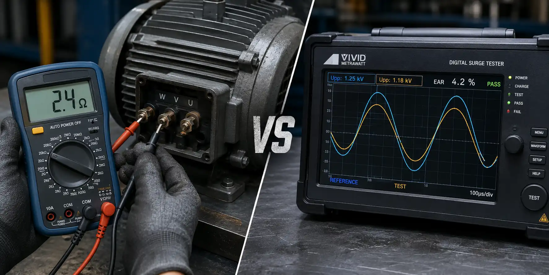
| What megger testing cannot find | Turn-to-turn and coil-to-coil faults (it measures winding-to-earth only) |
| Key standards | IEEE 43 · IEEE 522 · IEC 60034-27-1/-4 · NEMA MG1 Part 31 |
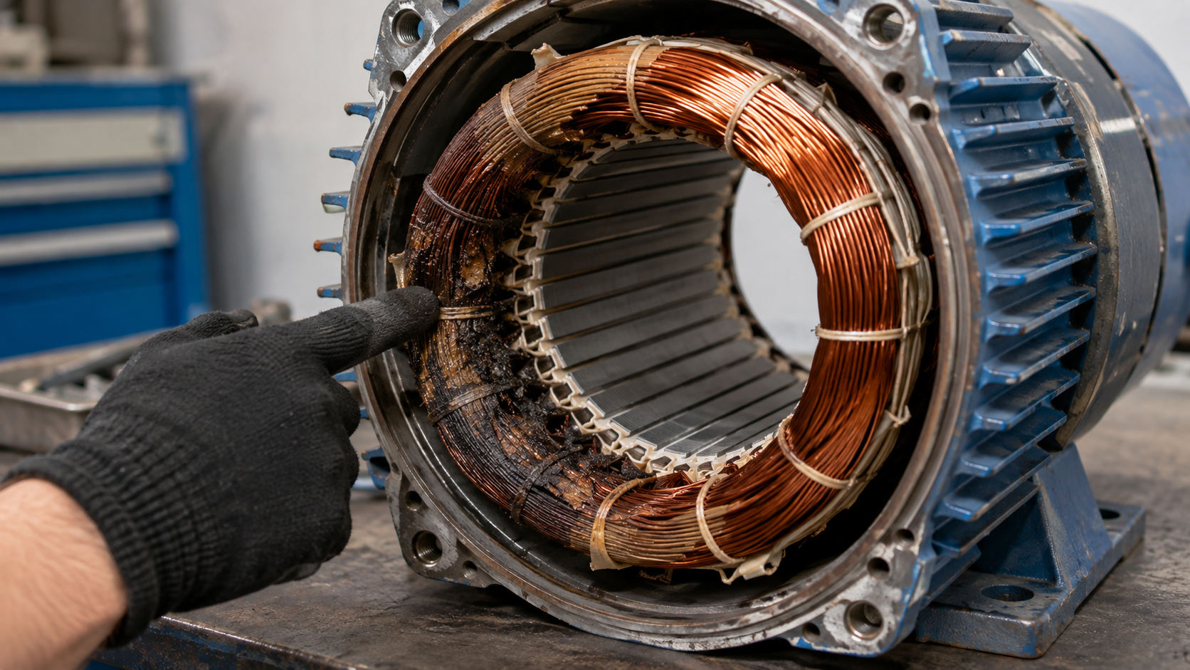
Motor winding failure begins as turn-to-turn insulation weakness that produces no visible symptom until it cascades into a phase-to-phase or phase-to-ground fault. The earliest reliable indicators are rising current draw, uneven phase temperatures and localised heating — but by the time these appear, the insulation is already compromised. Surge testing is the only routine method that detects turn-to-turn weakness before failure.
Winding faults announce themselves in three stages. Recognising which stage you’re in determines whether you have weeks to plan or hours to act.
Stage 1 — Electrical drift (weeks to months before failure)
Stage 2 — Thermal and mechanical symptoms (days to weeks)
Stage 3 — Terminal symptoms (act immediately)
The uncomfortable truth: by Stage 1, insulation degradation has already begun. Everything in Stage 3 is a post-mortem. This is why condition-based testing matters more than symptom watching.
Use this to decide what to test today, based on what the motor is actually doing.
| Symptom observed | Most likely cause | First test to run | Follow-up if inconclusive |
|---|---|---|---|
| Unbalanced phase currents | Turn-to-turn short, supply imbalance | Surge test | Motor circuit analysis (inductance/impedance) |
| Rising current, same load | Shorted turns, rotor bar issue | Surge test | ESA / rotor bar test |
| Overload trips at start only | Weak insulation stressed by inrush | Surge test at rated impulse | Hi-pot after surge |
| Ground fault trip | Ground-wall insulation breakdown | Insulation resistance (megger) | DC hi-pot, step-voltage |
| Low IR reading after washdown | Moisture ingress | IR + Polarisation Index | Dry out, retest, then PI |
| Low IR, low PI, stable over time | Contamination (dust, salt, carbon) | PI test | Clean, dry, retest |
| Burning smell, motor still runs | Advanced insulation breakdown | Stop the motor. IR test | Full teardown inspection |
| Localised hot spot on thermography | Shorted turns or loose connection | Surge test + connection check | Partial discharge testing |
| Noise/vibration increase | Unbalanced magnetic pull from winding fault | Surge test | Vibration analysis + ESA |
| Repeated failures after rewind | Poor rewind quality or upstream cause | Surge test on new winding | Power quality survey |
Read the pattern, not the single reading. A motor that passes every test today but has trended downward across three inspections is in worse shape than one with a stable, mediocre number.
The Montsinger rule governs everything here: for every 10 °C of sustained operation above the insulation class rating, expected life is roughly halved. A Class F motor run continuously 20 °C hot doesn’t lose a little life — it loses roughly three-quarters of it.
| Insulation class | Max winding temperature |
|---|---|
| Class A | 105 °C |
| Class B | 130 °C |
| Class F | 155 °C |
| Class H | 180 °C |
Root causes: overloading, blocked cooling paths, high ambient temperature, excessive start frequency, and voltage imbalance (a 3% imbalance can raise winding temperature by around 25%).
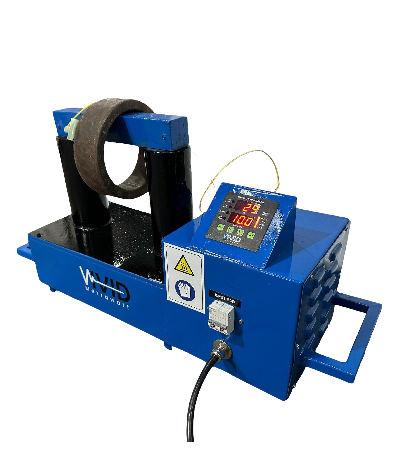
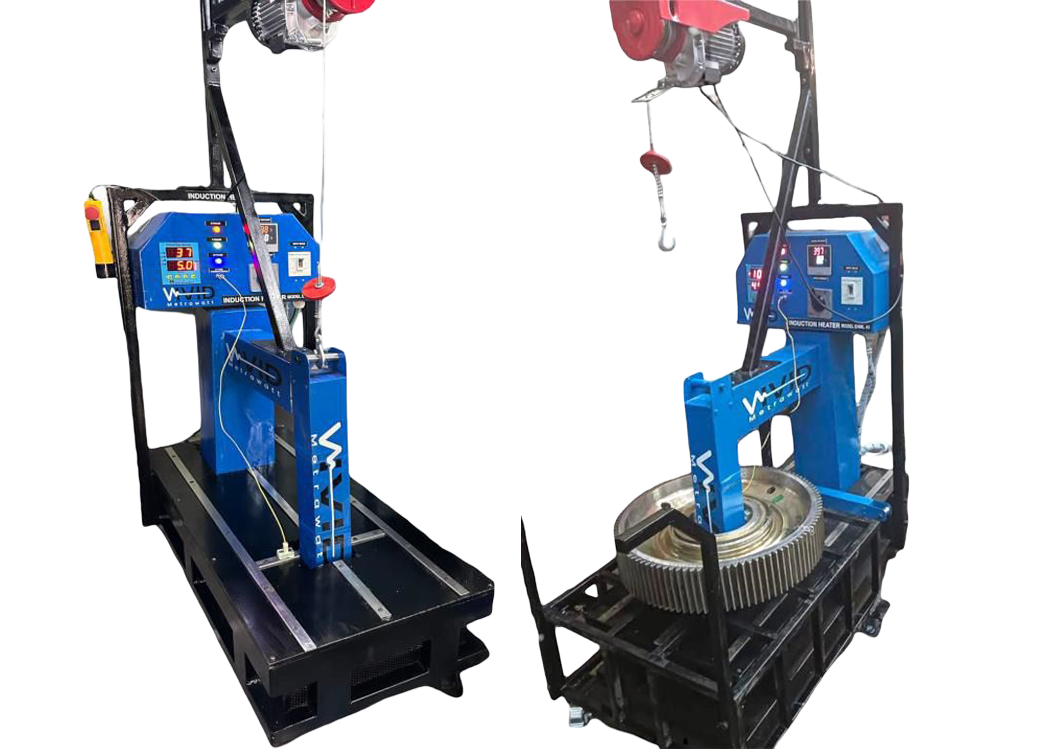
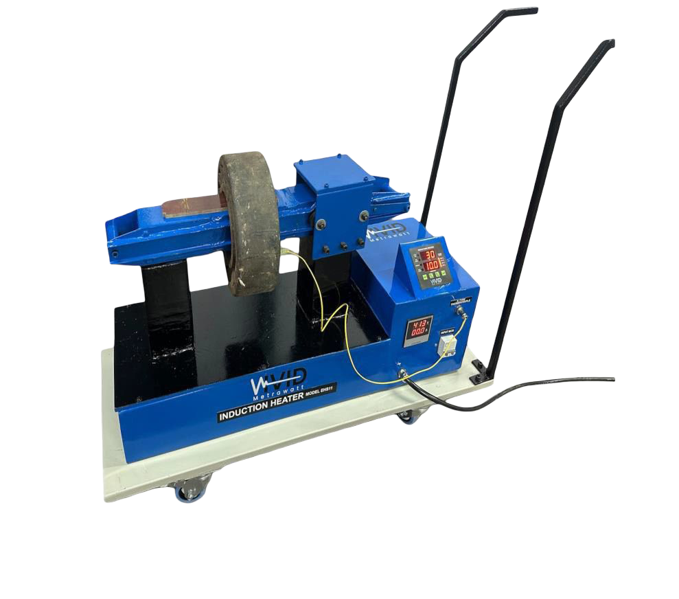
Bearing condition sits upstream of many “winding” failures — which is why correct mounting practice, covered in our bearing induction heater guide, is a genuine winding-reliability measure and not a separate topic.
This is the fastest-growing winding failure mode in modern plants, and it is frequently misdiagnosed as poor motor quality.
The mechanism: a VFD’s IGBT output switches with rise times measured in tens of nanoseconds. When that fast-rising pulse travels down a motor cable and hits the motor’s higher impedance, part of it reflects back. The reflected wave superimposes on the incoming pulse and can produce peak voltages approaching twice the DC bus voltage at the motor terminals.
Why it damages the first turns specifically: a fast-rising pulse does not distribute evenly across the winding. A disproportionate share of the voltage appears across the first few turns of the first coil. Those turns age far faster than the rest of the winding.
Contributing factors:
| Factor | Effect |
|---|---|
| Longer motor cable | More reflection, higher terminal peak |
| Faster IGBT rise time | Higher dV/dt stress |
| Higher switching frequency | More stress events per second |
| Non-inverter-duty insulation | No corona-resistant magnet wire |
Mitigation:
Because this damage is concentrated in the first turns and invisible to insulation resistance testing, surge testing is effectively the only routine detection method.
| Test | Detects | Does NOT detect | Typical use |
|---|---|---|---|
| Insulation resistance (megger) | Ground-wall deterioration, moisture, contamination | Turn-to-turn faults | Routine, first-line check |
| Polarisation Index | Contamination vs moisture, insulation condition trend | Localised defects | Complement to IR |
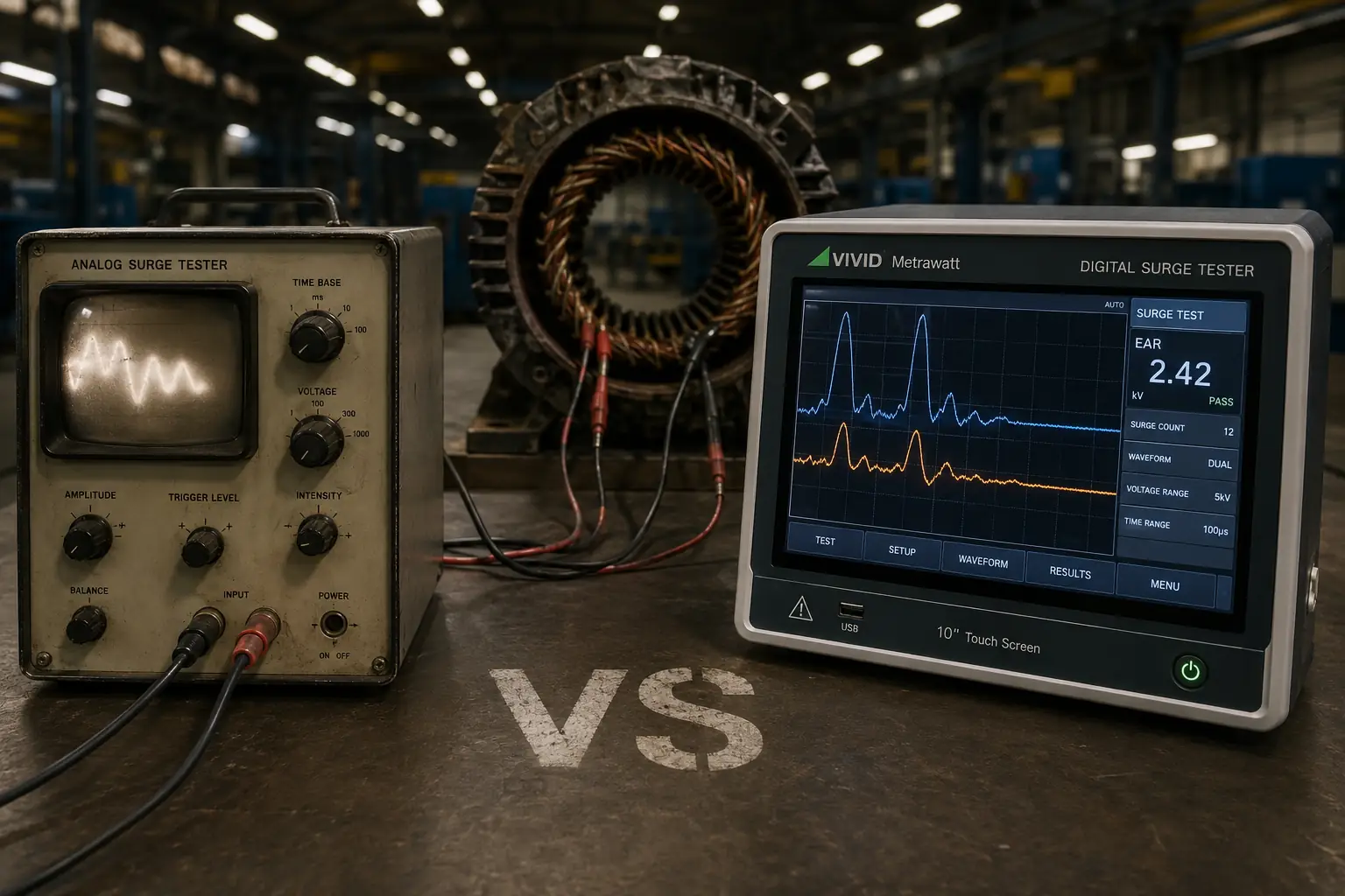
| Surge test | Turn-to-turn, coil-to-coil, phase-to-phase weakness | Ground-wall condition alone | Incoming QC, post-rewind, PdM |
| DC hi-pot | Ground insulation withstand, weak points | Turn-to-turn faults | Acceptance testing |
| AC hi-pot | Ground insulation under realistic stress | Turn-to-turn faults | Acceptance, type testing |
| Winding resistance | Open circuits, bad joints, gross imbalance | Insulation condition | Basic health check |
| Motor circuit analysis | Impedance/inductance imbalance, rotor issues | Precise insulation condition | Offline diagnostics |
| Partial discharge | Voids and ionisation in insulation | Early low-energy defects in LV motors | HV machines, critical assets |
| Thermography | Hot spots, loose connections | Internal turn faults | Online screening |
The pairing that catches nearly everything: insulation resistance for ground-wall condition + surge testing for turn insulation. Neither substitutes for the other. Our breakdown of surge testing vs hi-pot testing explains why combined-function instruments have become standard in rewind shops.
For deeper diagnostics, motor circuit analysis and electrical signature analysis extend coverage to rotor and supply-side faults that winding tests alone will miss.
Apply test voltage continuously for 10 minutes. Record at 1 minute and 10 minutes. PI = R₁₀ / R₁.
Note: PI is unreliable on modern epoxy-mica systems with very high IR; if the 1-minute reading exceeds several gigohms, IEEE 43 permits treating PI as not required.
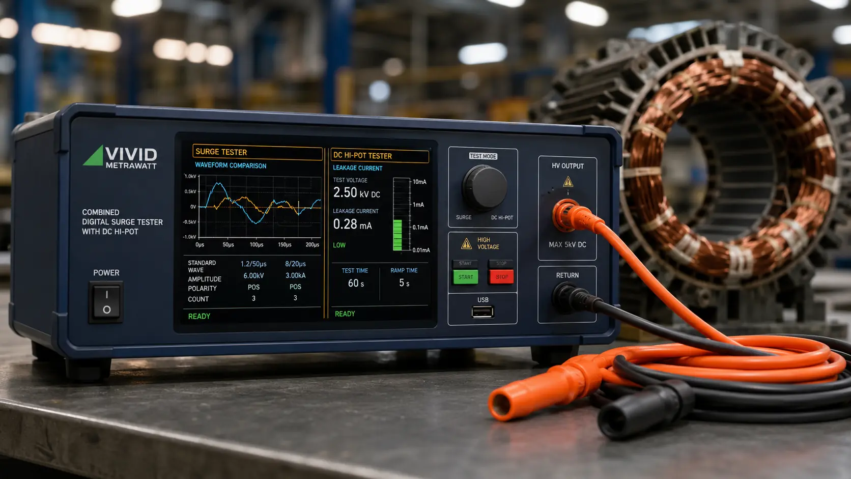
Instruments such as the VM5K–VM6K digital surge tester or the 5kV/6kV digital surge tester with DC hi-pot combine surge and hi-pot in one workflow, which matters when test-bay time is the constraint.
Apply sustained voltage per the applicable standard and monitor leakage current. A steadily rising leakage current indicates progressive breakdown — stop the test. Perform hi-pot after the surge test, never before, so you don’t stress ground insulation that surge testing might have flagged.
| Result pattern | Likely condition | Action |
|---|---|---|
| Normal IR, abnormal surge waveform | Turn-to-turn weakness | Increase monitoring; plan rewind |
| Low IR, normal surge waveform | Ground-wall contamination or moisture | Clean, dry, retest |
| Low IR and low PI | Moisture ingress | Dry out; investigate sealing |
| Low IR, PI still above 2.0 | Surface contamination | Clean; retest |
| All values declining steadily | General insulation ageing | Schedule replacement at next outage |
| Sudden drop after an electrical event | Transient damage | Immediate inspection before restart |
| Phase imbalance in inductance | Turn short or rotor issue | Motor circuit analysis |
Always record ambient temperature and humidity with every reading. Uncorrected data is the most common reason trending programmes fail to spot real degradation.
For high-value or high-voltage machines where you need to see insulation deterioration even earlier, partial discharge testing can flag void activity months ahead of conventional methods.
| Motor criticality | Visual inspection | Electrical testing | Surge test |
|---|---|---|---|
| Critical (no spare, stops production) | Monthly | Quarterly | Quarterly |
| Essential (spare available) | Quarterly | Semi-annual | Semi-annual |
| Non-critical | Semi-annual | Annual | Annual |
| VFD-driven (any tier) | — | Increase frequency one tier | Increase one tier |
Always test at these four moments, regardless of schedule:
A note on the economics: the value of a testing programme is not the cost of the tester versus the cost of a motor. It is the cost of the tester versus the cost of unplanned downtime on the process that motor drives. In continuous-process plants, that ratio is rarely close.
The earliest reliable indicators are increased current draw at constant load, phase current imbalance beyond about 2%, and localised temperature rise. Burning smells, visible discoloration and ground faults are late-stage signs — by then the insulation has already failed.
No. Insulation resistance testing measures insulation between the winding and earth. A turn-to-turn short occurs within the same phase and typically produces a normal megger reading. Surge testing is required to detect it.
IEEE 522 specifies 2 × rated line voltage + 1000 V. For a 415 V motor, that gives approximately 1830 V. Always confirm against the machine’s specification and any rewind house limits.
IEEE 43 recommends a minimum of 100 MΩ for new or newly rewound windings and 5 MΩ for older in-service machines, both corrected to 40 °C. Trend direction matters more than the absolute number.
Critical motors: quarterly. Essential motors: semi-annually. Non-critical motors: annually. Increase frequency by one tier for VFD-driven motors and for machines in hot, humid or contaminated environments.
Fast IGBT switching creates reflected voltage waves at the motor terminals that can approach twice the DC bus voltage. This stress concentrates on the first turns of the first coil. Inverter-duty insulation, dV/dt filters and shorter cable runs mitigate it.
Yes, when performed at the correct voltage by trained personnel. If insulation is already severely compromised, a high-voltage test may precipitate failure — which is far preferable to that failure occurring under load in production.
Always. Test before installation. Surge testing a rewound stator takes minutes and catches winding errors, damaged magnet wire and inadequate phase separation before the machine is committed to service.