Every experienced welding engineer has seen it: a weld that looks perfect on the surface, passes visual inspection, and then develops a delayed crack 48 hours later. The cause is almost always the same — an inadequate preheat temperature that allowed hydrogen to become trapped in the heat-affected zone as the metal cooled too quickly. Calculating the correct preheat temperature for welding is not guesswork — it is a disciplined engineering calculation based on the steel’s carbon equivalent, section thickness, hydrogen level, and heat input. This guide walks you through the complete calculation process, explains the critical variables, and shows how induction heating delivers the precision needed to apply that calculated temperature with confidence.
📋 Table of Contents
Before addressing how to calculate preheat temperature, it is essential to understand precisely what that temperature is doing — because this understanding is what separates a competent welding engineer from one who simply follows a table.
When steel is welded, three simultaneous problems are created in the heat-affected zone (HAZ):
Preheating addresses all three simultaneously: it slows the cooling rate (reducing martensite formation), allows more time for hydrogen to diffuse out of the HAZ, and reduces the thermal gradient that creates residual stresses. The required preheat temperature is the minimum that adequately addresses all three risks for the specific combination of material, thickness, consumable, and heat input being used.
For a full treatment of these mechanisms, read our detailed guide: What is Induction Preheating and Why Does It Matter in Welding?
Every preheat calculation method — whether the EN 1011-2 CEN method, the IIW CE method, or the AWS D1.1 tables — is ultimately a function of the same four variables:
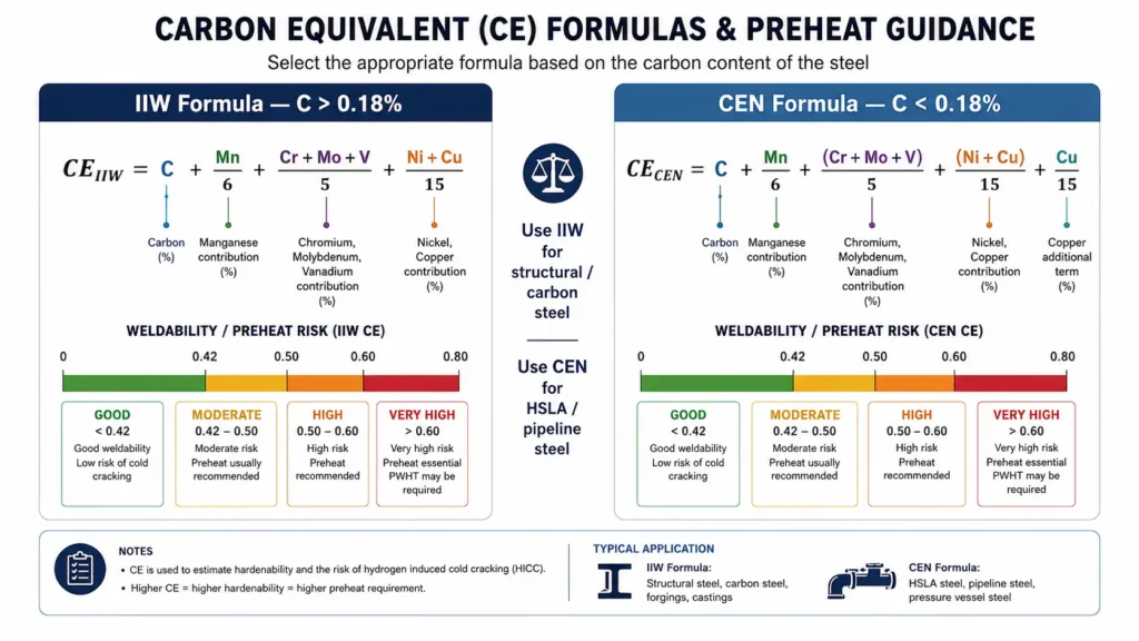
The chemical composition of the base metal is the primary determinant of hardenability — and therefore cracking risk. Carbon is the dominant element, but manganese, chromium, molybdenum, vanadium, nickel, and copper all contribute. The carbon equivalent formula combines these into a single index that predicts hardening behaviour.
Thicker sections act as a larger heat sink — they extract heat from the weld zone more rapidly, producing faster cooling rates and more severe HAZ hardening. The combined thickness at the joint (not just the plate thickness) is used in calculation.
The hydrogen designation of the welding consumable — expressed in ml of hydrogen per 100g of deposited metal — directly affects how much atomic hydrogen enters the weld pool. Lower hydrogen processes (basic low-hydrogen SMAW, GMAW, GTAW) require lower preheat than higher-hydrogen processes (cellulosic SMAW, some flux-cored wires).
Higher heat input slows the cooling rate — partly compensating for hardenability. Lower heat input processes (TIG root passes, small-diameter SMAW passes) cool more rapidly and may require higher preheat than a high-heat-input SAW weld on the same material.
Understanding how these variables interact is the foundation of both preheat calculation and proper heat treatment selection for different steel materials.
There are two widely used carbon equivalent formulas. Understanding which to use — and why — is the first step in a rigorous preheat calculation.
The International Institute of Welding (IIW) formula is most accurate for steels with carbon content above 0.18%:
The CEN formula (also called the Pcm or Ito-Bessyo formula) is more accurate for modern low-carbon microalloyed steels (C < 0.18%), which are common in structural and pipeline applications:
The CEN value feeds directly into the EN 1011-2 preheat temperature calculation (Section 4 below).
Which formula to use?
EN 1011-2 Annex B provides the most rigorous and internationally recognised method for calculating minimum preheat temperature. The formula is:
Where:
Combined thickness accounts for the heat sink effect of the joint geometry:
| HD Scale | Max H₂ (ml/100g) | Value Used in Formula | Typical Process |
|---|---|---|---|
| A | ≤ 5 | 3.5 | GTAW, high-quality MIG/MAG |
| B | ≤ 10 | 7.5 | Low-hydrogen SMAW (basic) |
| C | ≤ 15 | 12 | Standard SMAW, FCAW |
| D | ≤ 25 | 20 | Cellulosic SMAW (pipeline root) |
Important: The HD value assumes the consumable is properly stored, handled, and dried as per manufacturer’s instructions. Improperly stored or wet consumables have hydrogen levels significantly above their designations — making the calculated preheat inadequate regardless of how accurately it was calculated.
AWS D1.1 (Structural Welding Code — Steel) provides a more simplified approach, using material category (based on carbon equivalent), combined thickness, and minimum specified yield strength to look up minimum preheat temperatures from prescriptive tables.
| Category | CE Range | Thickness ≤ 19mm | 19–38mm | 38–64mm | > 64mm |
|---|---|---|---|---|---|
| A | < 0.40 | None req. | None req. | None req. | 10°C |
| B | 0.40–0.45 | None req. | 10°C | 65°C | 110°C |
| C | 0.45–0.55 | 10°C | 65°C | 110°C | 150°C |
| D | > 0.55 | 65°C | 110°C | 150°C | 200°C |
Note: AWS D1.1 tables assume low-hydrogen consumables (H8 or lower — equivalent to HD scale B). For higher-hydrogen consumables, the tabulated temperatures must be increased. The EN 1011-2 method is generally preferred for complex or critical applications because it explicitly accounts for hydrogen level in the calculation rather than assuming a fixed designator.
Let us work through a complete calculation for a realistic structural welding scenario:
Scenario: 40mm butt weld in S355J2 structural steel, SMAW process, standard basic electrode
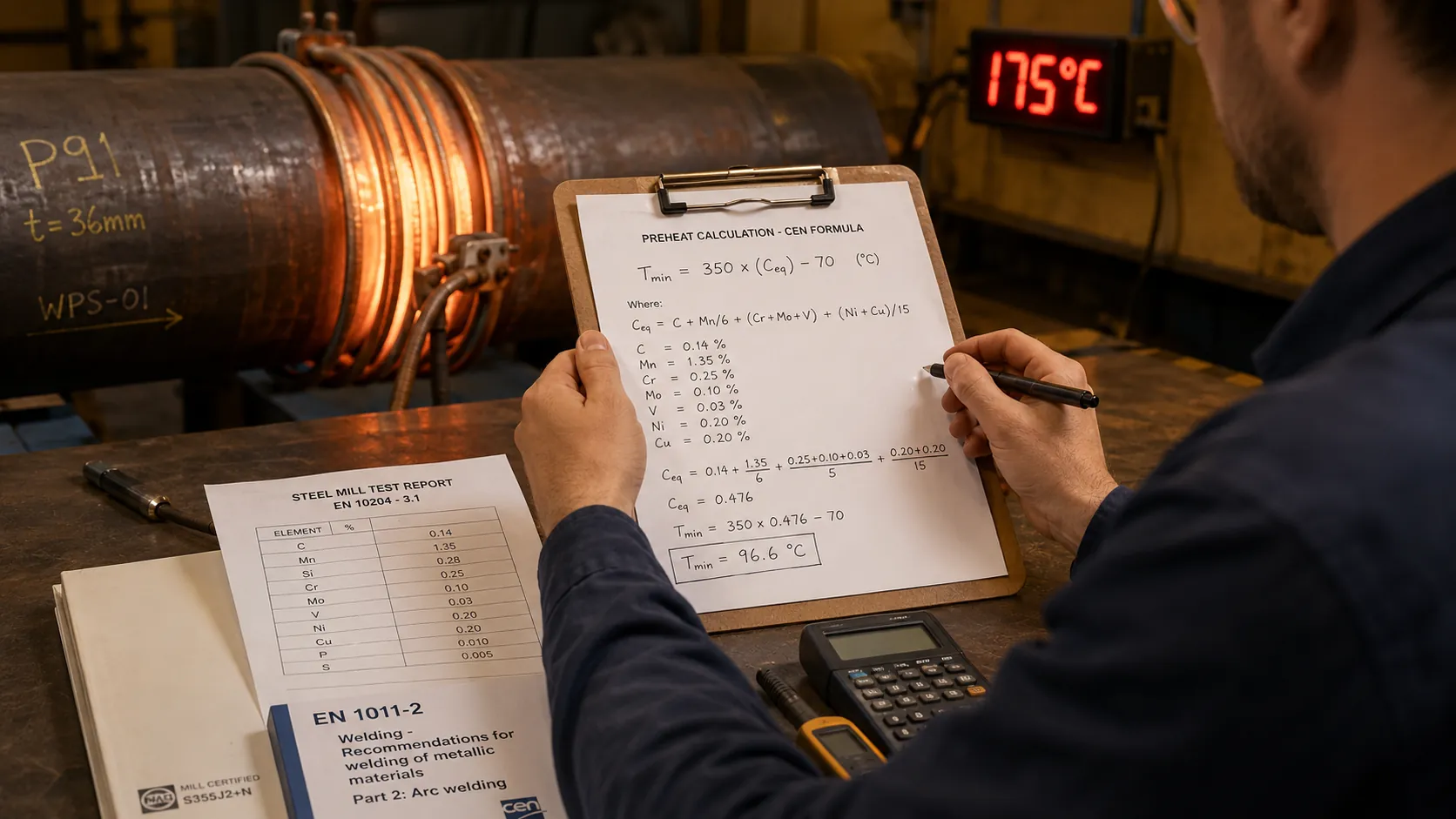
Step 1 — Obtain chemical composition from mill test report (typical S355J2):
C = 0.14%, Mn = 1.50%, Si = 0.35%, Cr = 0.03%, Mo = 0.01%, V = 0.01%, Ni = 0.02%, Cu = 0.02%, B = 0.0003%
Step 2 — Calculate CEN (EN 1011-2 formula, since C < 0.18%):
CEN = 0.14 + (1.50 + 0.35)/10 + (0.03 + 0.01 + 0.01)/20 + (0.02 + 0.02)/40 + (5 × 0.0003)
CEN = 0.14 + 0.185 + 0.0025 + 0.001 + 0.0015
CEN = 0.33
Step 3 — Combined thickness (d):
Butt weld in 40mm plate: d = 40mm
Step 4 — Hydrogen designation:
Standard basic (low hydrogen) SMAW electrode, properly dried: HD = B → use value 7.5
Step 5 — Apply EN 1011-2 formula:
Tp0 = 697 × 0.33 + 160 × tanh(40/35) + 62 × 7.50.35 − 328
Tp0 = 230.0 + 160 × tanh(1.143) + 62 × 2.31 − 328
Tp0 = 230.0 + 160 × 0.817 + 143.2 − 328
Tp0 = 230.0 + 130.7 + 143.2 − 328
Tp0 = 175.9°C → round up to 175°C (or nearest 25°C = 200°C, conservative approach)
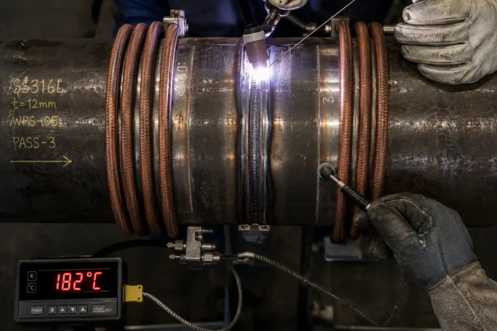
Result: Minimum preheat temperature of 175–200°C for this joint. Apply induction heating to achieve and maintain this temperature across the full weld zone before striking the first arc and between each welding pass.
⚠️ Engineering Note
This calculation gives the minimum preheat. Real-world applications should add a conservative margin of 25–50°C above the calculated value to account for: consumable moisture absorption (especially in humid environments), heat loss to ambient air, inaccuracies in the mill test report composition, and any uncertainty about the exact welding heat input being used.
The EN 1011-2 formula assumes ambient conditions above 5°C. For colder environments:
The EN 1011-2 formula assumes a heat input of 1.5–3.5 kJ/mm as the standard range. Corrections apply:
Highly restrained joints — such as nozzle welds in pressure vessels, repair welds in existing fabrications, or welds in stiff structural frames — have higher residual stress levels and therefore higher cracking risk. For high-restraint joints, increase the calculated preheat by 25–50°C as a conservative engineering margin.
This is one reason why proper induction preheating for welding — which maintains the temperature uniformly across the entire joint, including the restrained sections — is so important in pressure vessel and pipeline fabrication.
Preheat and inter-pass temperature are often confused — but they serve different purposes and have different control requirements.
| Parameter | Preheat | Inter-Pass Temperature |
|---|---|---|
| When applied | Before first arc strike | Between each welding pass |
| Control type | Minimum value | Min and Max value |
| Typical minimum | Calculated Tp0 | Equal to preheat minimum |
| Typical maximum | No maximum (preheat only) | 250°C (carbon steel), 350°C (Cr-Mo) |
| Risk if too low | Hydrogen cracking, HAZ hardening | Same as inadequate preheat |
| Risk if too high | N/A for preheat | Grain growth, reduced toughness, HAZ sensitisation (stainless) |
Induction heaters with closed-loop temperature control are particularly valuable for inter-pass temperature management in multi-pass welds — maintaining the minimum value between passes without risk of exceeding the maximum, which can be difficult to control with torch heating.
For more on this topic see: Smart Induction Heating — Precision and Efficiency in Industry
Calculating the correct preheat temperature is only half the challenge. The other half is applying it with sufficient uniformity, speed, and control that the temperature at the weld zone — not just at the surface measured by the thermocouple — genuinely meets the minimum requirement. This is where method selection makes the difference between theoretical compliance and actual weld quality assurance.
For a full technology comparison, read: Induction Heating vs. Resistance Heating — Which Technology Is Superior?
EN ISO 13916 specifies that preheat temperature should be measured on the opposite face of the joint from the heat source, at a distance of 75mm from the fusion line (for thicknesses > 50mm) or 4× the material thickness from the fusion line (for thicknesses ≤ 50mm). This ensures that the measurement reflects the true thermal state of the joint — not just the heated surface.
Induction heating’s through-thickness heat generation means that the temperature difference between the heated surface and the measured opposite face is smaller than for surface heating methods — providing greater confidence that the minimum preheat is genuinely being achieved through the full section.
For induction equipment selection guidance: How to Select an Induction Heater for Steel Heat Work
For safety requirements of your equipment: What Safety Features Should You Look for in an Induction Heater?
The following table provides indicative minimum preheat temperatures for common steel grades. Always verify against the specific steel’s certified chemical analysis and the applicable welding standard — these values assume low-hydrogen consumables (HD = B) and standard section thicknesses.
| Steel Grade | Typical CE / CEN | ≤ 25mm | 25–50mm | 50–75mm | Standard |
|---|---|---|---|---|---|
| S235 / A36 | < 0.38 | None | None | 50°C | EN 1011-2 / AWS D1.1 |
| S355 / A572 Gr50 | 0.33–0.43 | None–50°C | 75–150°C | 150–200°C | EN 1011-2 |
| API 5L X65 | 0.38–0.43 | 50°C | 100°C | 150°C | API 1104 |
| 4130 / SA-335 P11 | 0.55–0.65 | 150°C | 200°C | 250°C | ASME B31.3 |
| SA-335 P22 (2.25Cr-1Mo) | 0.65–0.75 | 200°C | 250°C | 300°C | ASME B31.1 |
| SA-335 P91 (9Cr-1Mo-V) | > 0.80 | 200°C | 250°C | 300°C | ASME Section I |
| Duplex SS (2205) | N/A | None* | None* | None* | EN 1011-3 |
* Duplex stainless steels typically do not require preheat and should not exceed 100°C inter-pass to avoid sigma phase precipitation.
Also see our guide on materials and their heat treatment characteristics: What Are the Common Materials for Induction Hardening? and What Is the Induction Hardening Process?
The most rigorous international method uses the EN 1011-2 CEN formula: CEN = C + (Mn+Si)/10 + (Cr+Mo+V)/20 + (Ni+Cu)/40 + 5B, then applies the preheat temperature formula: Tp0 = 697 × CEN + 160 × tanh(d/35) + 62 × HD0.35 − 328. This accounts for steel chemistry, section thickness, and hydrogen content. AWS D1.1 provides a simpler look-up table method for structural steels.
Carbon Equivalent (CE) is a single numerical index that combines the effect of carbon and other alloying elements to predict a steel’s hardenability and susceptibility to hydrogen-induced cracking during welding. A higher CE requires higher preheat to reduce cracking risk.
For S235/A36 mild steel below 25mm thickness with low-hydrogen consumables in warm conditions: typically no preheat is required. Above 50mm or in cold conditions: 50°C minimum. Always verify against the specific mill test report CE and applicable standard.
Preheat is the minimum temperature before the first welding pass — a minimum requirement. Inter-pass temperature is measured between each subsequent pass — it has both a minimum (equal to preheat) and a maximum (to prevent overheating and grain growth, typically 250°C for carbon steel).
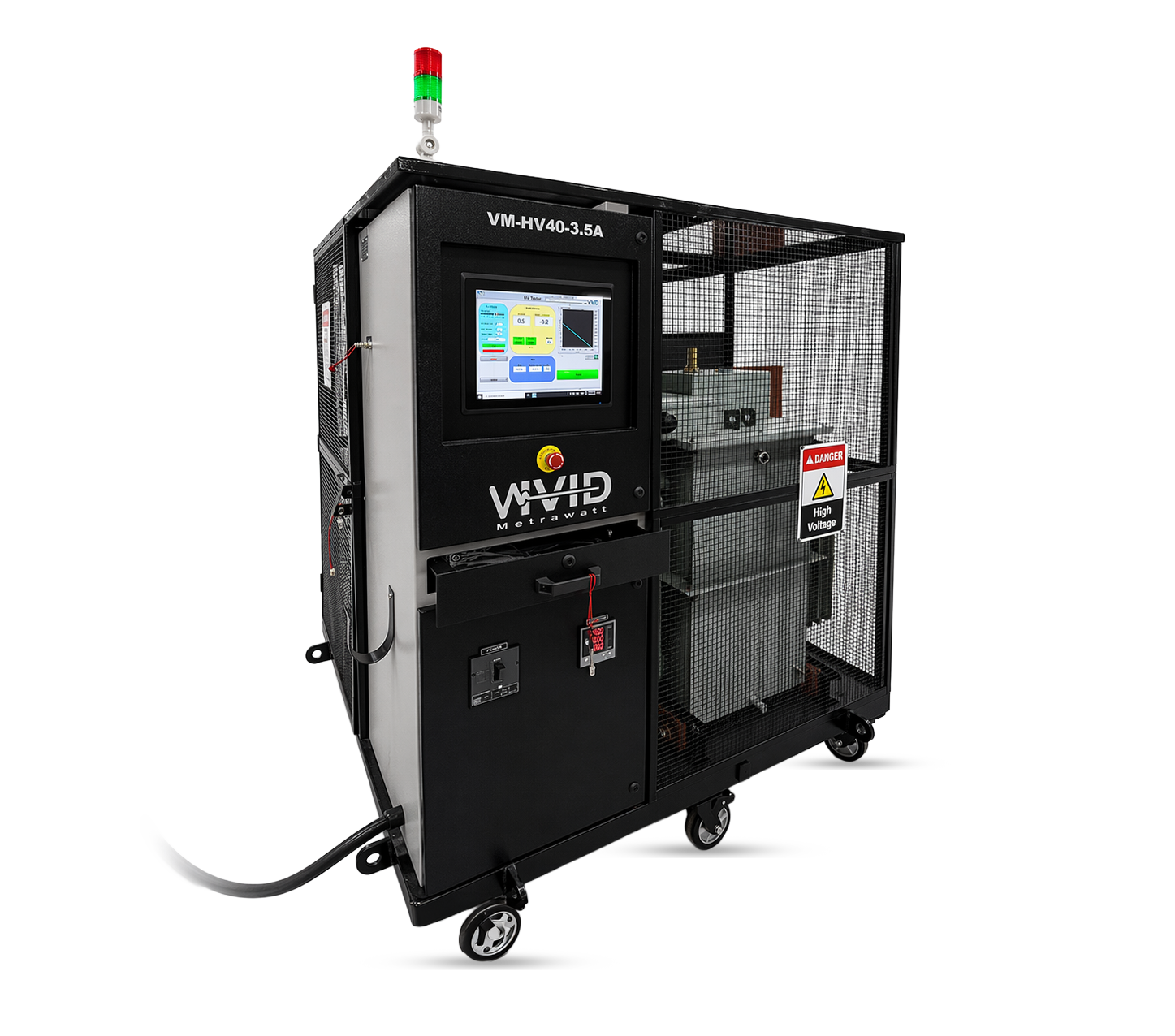
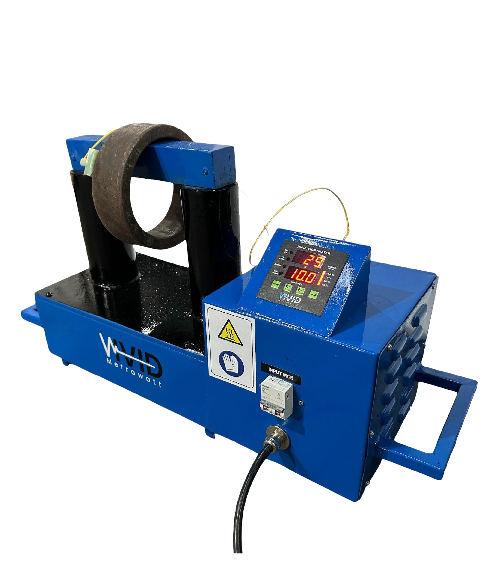
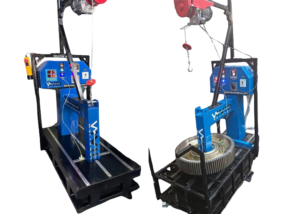
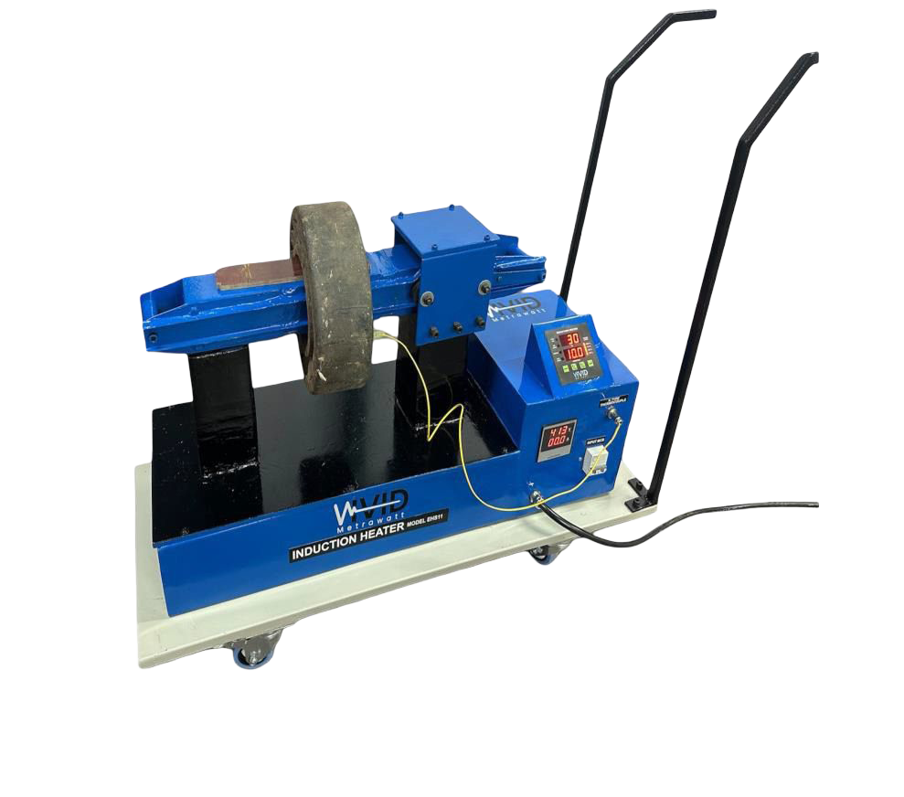
Induction heating delivers fast, uniform through-thickness heating via electromagnetic eddy currents, with closed-loop thermocouple control maintaining the target temperature within ±5°C. It is the most precise, portable, and energy-efficient method for achieving and documenting code-compliant preheat on any weld joint.
Yes. Below 5°C ambient temperature, most codes require a minimum 25°C increase to the calculated preheat. In cold climates or outdoor winter welding, the actual required preheat may be 50°C above the calculation-based minimum. Induction heating’s rapid heat-up capability is particularly valuable in these conditions.
Calculating the correct preheat temperature for welding is a rigorous engineering exercise — one that requires the steel’s actual chemical composition, an understanding of the consumable’s hydrogen level, and careful application of the appropriate standard’s methodology. The CEN formula and EN 1011-2 method provide the most accurate results for modern structural and pipeline steels; the AWS D1.1 tables offer a practical simplified approach for standard structural applications.
But the calculation is only the beginning. Induction preheating is what turns a correctly calculated temperature into a correctly applied one — uniformly, rapidly, and with the thermocouple-verified documentation that a Welding Procedure Specification and quality record require.
Whether you are welding 40mm S355 structural joints, Cr-Mo pressure piping, or API 5L pipeline steels, Vivid Metrawatt’s induction heating systems deliver the precision that your preheat calculation demands. The same system handles inter-pass temperature maintenance throughout the weld sequence — and post-weld heat treatment (PWHT) after welding is complete.
Continue building your technical knowledge with these related guides:
🔥 Apply Your Calculated Preheat With Confidence
Vivid Metrawatt’s portable induction heating systems deliver the temperature precision, documentation, and portability that welding engineers require — on site, in the workshop, or in the field.