
Last updated: August 2026 · Reviewed by the Vivid Metrawatt engineering team, Mumbai
Table of Contents
Electromagnetic induction is the generation of an electromotive force (EMF) in a conductor when the magnetic flux through it changes. Discovered by Michael Faraday in 1831, it converts mechanical or magnetic energy into electrical energy — and is the operating principle behind every generator, transformer, induction motor and induction heater in use today.
| Discovered by | Michael Faraday, 1831 (Joseph Henry independently, same period) |
| Faraday’s Law | ε = −N × dΦ/dt |
| Lenz’s Law | Induced current opposes the change that created it (the minus sign) |
| Unit of magnetic flux | Weber (Wb); flux density in tesla (T) |
| Two heating mechanisms | Eddy current (I²R) loss + hysteresis loss (ferromagnetic materials only) |
| Skin depth formula | δ = √(ρ / π·f·μ) |
| Curie temperature (steel) | ≈ 770 °C — magnetic permeability collapses above this point |
| Modern generator efficiency | Over 90% mechanical-to-electrical conversion |
Electromagnetic induction occurs when the magnetic flux passing through a conductor changes. That change drives free electrons in the conductor, producing an electromotive force. If the conductor forms a closed circuit, current flows.
The requirement is change, not motion. You can produce induction by:
Entity summary (Entity–Attribute–Value):
| Entity | Attribute | Value |
|---|---|---|
| Electromagnetic induction | Discovered by | Michael Faraday |
| Electromagnetic induction | Year of discovery | 1831 |
| Faraday’s Law | Governs | Magnitude of induced EMF |
| Lenz’s Law | Governs | Direction of induced current |
| Magnetic flux | SI unit | Weber (Wb) |
| Eddy currents | Cause | Changing flux in a conductive body |
| Skin depth | Inversely proportional to | Square root of frequency |
In 1831, Michael Faraday wound two separate coils on opposite sides of an iron ring. When he connected one coil to a battery, a current appeared momentarily in the second coil — but only at the instant of connection or disconnection.
That observation was decisive. A steady current produced nothing. Only a changing current — and therefore a changing magnetic field — induced anything in the second coil. Faraday had built the first transformer and identified the principle behind every generator that would follow.
Joseph Henry, working in the United States, reached the same conclusion independently. Faraday published first and is generally credited.
Faraday’s Law states that the induced electromotive force in a circuit equals the negative rate of change of magnetic flux through that circuit.
ε = − dΦ/dt
For a coil of N turns:
ε = − N × dΦ/dt
Where:
What this means practically: the speed of the change determines the voltage. Doubling the rate of flux change doubles the EMF. Doubling the number of turns also doubles it. This single relationship explains transformer turns ratios, generator output scaling and why induction heating uses high frequencies.
Lenz’s Law states that the induced current flows in the direction that opposes the change producing it. Formulated by Heinrich Lenz in 1834, it is the reason for the negative sign in Faraday’s equation.
Push a magnet into a coil and the induced current creates a magnetic field that pushes back. You feel resistance. That resistance is not incidental — it is conservation of energy expressed mechanically.
Three consequences that matter in engineering:
| Factor | Effect on induced EMF | Engineering implication |
|---|---|---|
| Magnetic field strength | Higher field → higher EMF | Drives magnet and core material selection |
| Rate of flux change | Faster change → higher EMF | Governs frequency selection |
| Number of coil turns | More turns → proportionally higher EMF | Transformer and coil design |
| Coil area | Larger area intercepts more flux | Coil geometry |
| Core material | Ferromagnetic cores concentrate flux | Silicon steel, ferrite selection |
| Angle to the field | Maximum when perpendicular; zero when parallel | Rotor/coil orientation |
| Conductor resistivity | Lower resistivity → higher current for the same EMF | Copper vs aluminium windings |
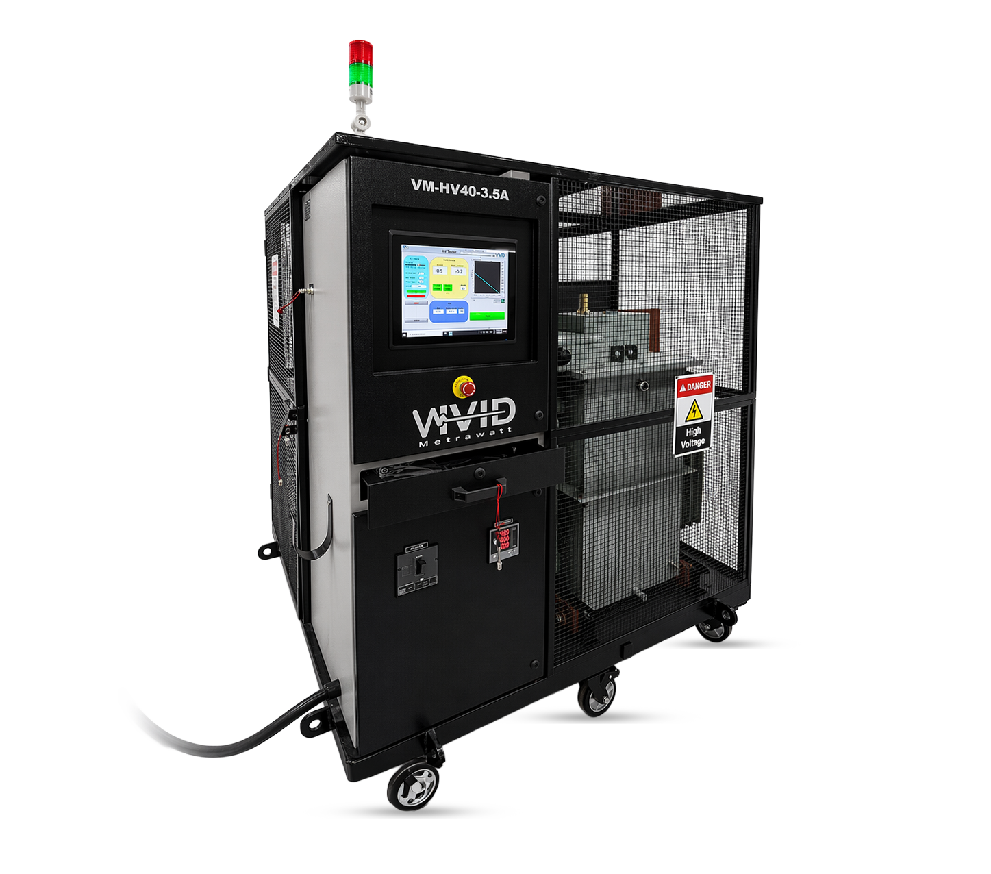
A design consequence worth noting: every one of these factors is set by the winding. Which is why manufacturers of motors, generators and transformers verify turn-to-turn insulation with a digital surge tester — a single shorted turn changes the effective N in Faraday’s equation and quietly degrades the machine’s output.
When a solid conductive body sits in a changing magnetic field, the induced currents have nowhere to go. They circulate in closed loops inside the metal. These are eddy currents, and they generate heat through the material’s own resistance.
In ferromagnetic materials — steel, iron, nickel — a second mechanism operates alongside:
Hysteresis loss. The alternating field repeatedly reverses the magnetic domains inside the metal. Each reversal consumes energy, which appears as heat.
| Eddy current loss | Hysteresis loss | |
|---|---|---|
| Occurs in | All conductive materials | Ferromagnetic materials only |
| Driven by | Induced circulating currents | Magnetic domain reversal |
| Scales with | Frequency² and flux density² | Frequency and flux density (Steinmetz relation) |
| Share in steel heating | Dominant contribution | Meaningful secondary contribution |
| Above Curie point | Continues | Disappears entirely |
Why this split matters commercially: ferrous parts heat faster than non-ferrous parts of identical geometry, because they get both mechanisms. Aluminium and copper heat by eddy currents alone — and their low resistivity makes them harder to heat, which is why non-ferrous induction applications need higher power density.
Induced current does not distribute evenly through a workpiece. It concentrates near the surface. This is the skin effect, and it is the concept that turns induction physics into a controllable industrial process.
Skin depth (δ) is the depth at which current density falls to about 37% of its surface value:
δ = √( ρ / (π · f · μ) )
Where:
The engineering takeaway: skin depth is inversely proportional to the square root of frequency. Raise the frequency and heating concentrates nearer the surface. Lower it and heat penetrates deeper.
| Frequency band | Penetration depth in steel | Typical application |
|---|---|---|
| 50–1,000 Hz (mains / low) | Deepest | Through-heating of large billets, bearings, shafts |
| 1–10 kHz (medium) | Moderate | Forging preheat, shrink fitting, larger case depths |
| 10–100 kHz (high) | Shallow | Surface hardening, brazing, small parts |
| > 100 kHz (radio frequency) | Very shallow | Thin-wall parts, wire, precision hardening |
This is precisely why selecting frequency is a design decision, not a default. Our comparison of low-frequency vs high-frequency induction heating works through the trade-offs application by application, and induction heating coil design covers how coil geometry shapes the resulting heat pattern.
At approximately 770 °C, steel loses its ferromagnetic properties. Its relative magnetic permeability drops from several hundred to roughly 1 — the same as air.
Three things happen at that instant:
Operators observe this as a distinct “stall” in the heating rate as steel passes through the Curie point. Well-designed power supplies compensate automatically. It is also the reason induction hardening processes must account for behaviour on both sides of that transition.
Almost all electricity generated worldwide — thermal, nuclear, hydro, wind, tidal — reaches the grid through electromagnetic induction. The energy source differs; the final conversion step does not. A turbine rotates conductors through a magnetic field, and EMF appears.
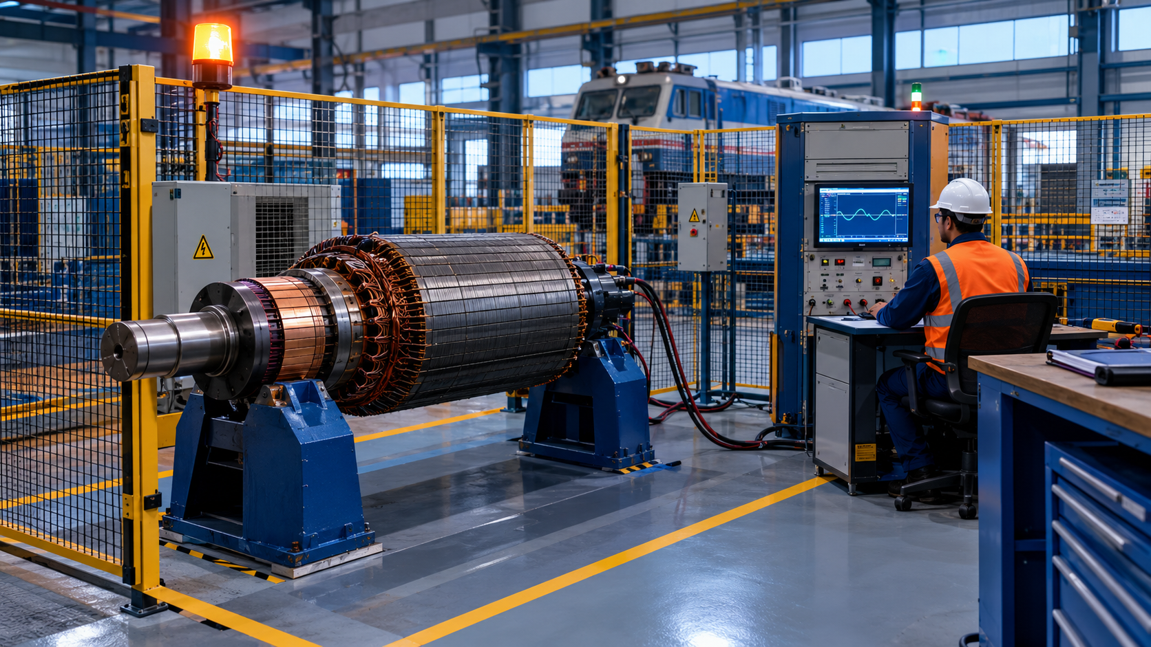
Because generator and alternator windings operate under continuous high-voltage stress, insulation integrity is validated before commissioning using equipment such as a 50kV digital surge tester or an automatic high-voltage tester.
Mutual induction between primary and secondary windings steps voltage up for transmission and down for distribution. Nothing moves — only the field changes.
A rotating stator field induces current in the rotor, which produces torque. Induction motors drive the majority of industrial machinery worldwide.
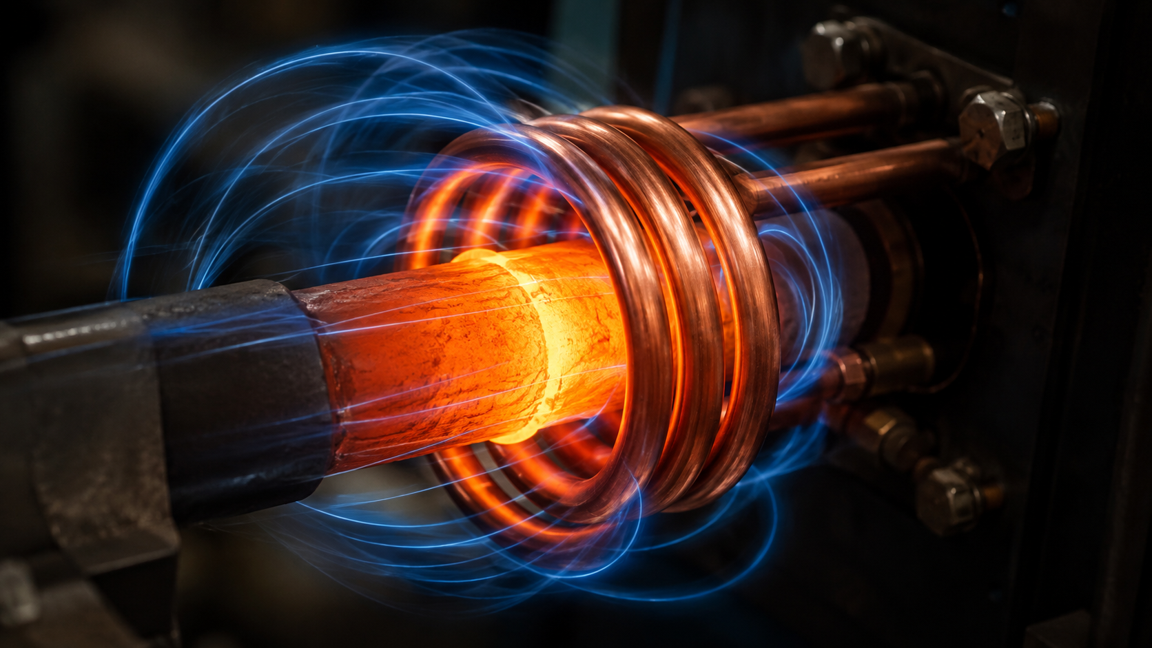
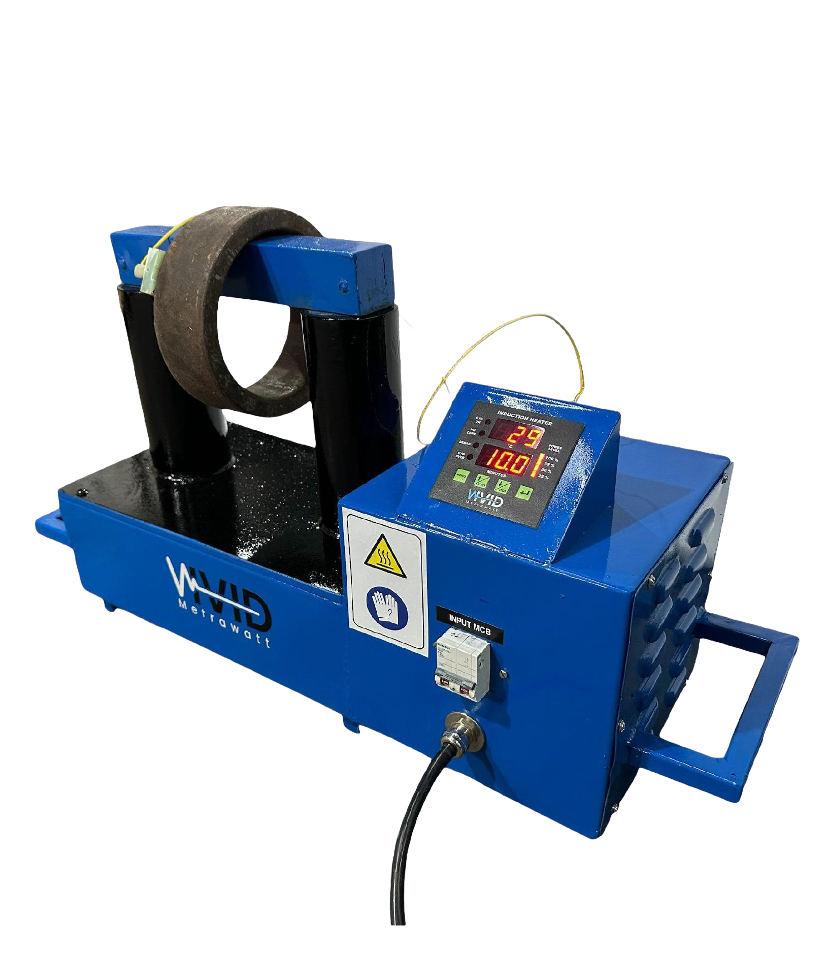
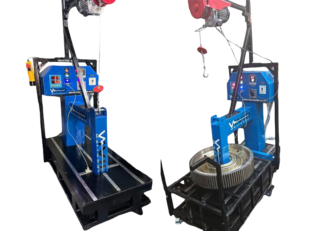
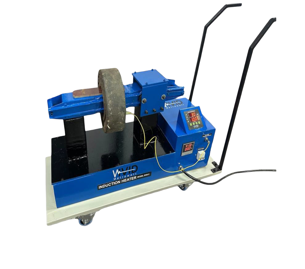
The most direct commercial application of the physics on this page:
Because this heating happens inside the workpiece rather than around it, it consistently outperforms conventional methods on both speed and energy use — the subject of our induction heating vs resistance heating comparison.
Induction cooktops, wireless chargers, electric toothbrush bases, metal detectors, guitar pickups and electromagnetic flow meters all run on the same 1831 discovery.
Electromagnetic induction is the production of voltage in a conductor when the magnetic field around it changes. If the conductor is part of a closed circuit, that voltage drives a current.
Michael Faraday discovered it in 1831 through experiments with two coils wound on an iron ring. Joseph Henry made the same discovery independently around the same period, but Faraday published first.
Faraday’s Law: ε = −N × dΦ/dt, where ε is induced EMF in volts, N is the number of turns, and dΦ/dt is the rate of change of magnetic flux in webers per second. The negative sign reflects Lenz’s Law.
Yes. A transformer produces induction with no moving parts — the alternating current in the primary winding creates a changing magnetic field, which is sufficient. Change in flux is required; physical motion is not.
Eddy current loss comes from circulating currents induced inside a conductive body and occurs in all conductors. Hysteresis loss comes from repeated reversal of magnetic domains and occurs only in ferromagnetic materials. Induction heating of steel produces both.
Skin depth is the depth at which induced current density falls to about 37% of its surface value, calculated as δ = √(ρ / πfμ). Higher frequencies produce shallower skin depth, concentrating heat near the surface.
That is steel’s Curie temperature. Above it, steel loses ferromagnetism, hysteresis heating stops, magnetic permeability drops to near that of air, and skin depth increases sharply — changing the entire heating characteristic.
Copper and aluminium are the preferred conductors for coils and windings, while ferromagnetic materials — iron, silicon steel and ferrite — are used to concentrate and direct magnetic flux in cores.
Frequency selection, coil geometry, skin depth and power density decide whether an induction system delivers a clean result or a scrapped part. Our engineers have specified induction heating and electrical testing systems for automotive, railway, power and heavy engineering plants across India and worldwide.
Discuss Your Application Explore Induction HeatersEngineering support • Application sizing • Global delivery

![Surge Testing for Wind Turbine Generators: Complete Guide [2026]](https://vividmetrawattglobal.com/wp-content/uploads/2026/09/a_wide_cinematic_industrial_outdoor_scene_at_an_o.webp)