Induction heating has transformed how automotive workshops handle bearing fits, bolt removal, and gear press-fits — reducing what once took hours of torch work to minutes of clean, controlled heating. Yet despite how capable the technology is, induction heater mistakes in automotive maintenance remain surprisingly common, even among experienced technicians. A wrong temperature setting here, an ill-fitted coil there, and you are looking at damaged bearings, stressed housings, and in the worst case, a motor that passes no post-service test. This guide breaks down the five most damaging mistakes, explains why they happen, and shows you exactly how to avoid them.
Modern automotive maintenance increasingly relies on precision heating for tasks like wheel bearing replacement, crankshaft gear fitting, differential assembly, axle shaft removal, and EV motor servicing. Compared to open-flame torch heating, induction heating delivers:
Learn more about how this technology is applied across sectors in our guide on induction heater for the automotive industry. The same precision principles apply whether you are servicing a passenger vehicle or a heavy-duty railway bogie — as explored in our deep-dive on best induction heating solution for railways.
But none of those advantages materialise if the equipment is used incorrectly. Let us look at where automotive technicians most often go wrong.
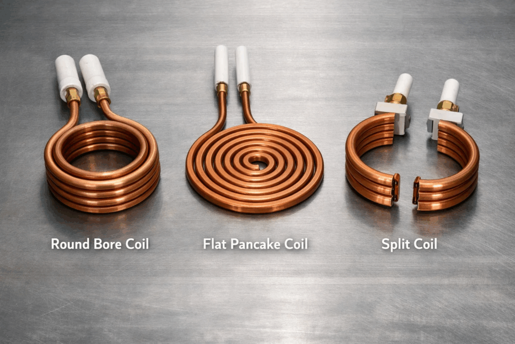
The Problem: Induction heating is coupling-dependent. The efficiency of heat transfer depends directly on how closely the coil matches the geometry of the workpiece. Many technicians use a single all-purpose coil for every task, whether they are heating a small needle bearing, a large wheel hub bearing, or a crankshaft gear — and the results are invariably poor.
Why It Happens: Workshop environments are fast-paced. Swapping coils takes time, and when a technician is under pressure, they default to whatever is already on the machine.
What Goes Wrong:
The Fix:
Key Takeaway: Correct coil geometry is the single most impactful variable in whether induction heating is precise or damaging. It is not an afterthought — it is the foundation of a safe setup.
For broader guidance on matching equipment capability to material and workpiece requirements, see our resource on how to select an induction heater for steel heat work.
The Problem: Every bearing, gear, and metal component has a maximum safe heating temperature before metallurgical damage occurs. For most automotive bearings (typically chrome steel, GCr15 or SAE 52100), this is 110–120°C (230–248°F). Aluminium housings, light-alloy gearbox casings, and EV motor components have even lower thresholds. Overheating is one of the most destructive — and most common — induction heater mistakes in automotive maintenance.
Why It Happens: Many older or budget induction heaters lack precise temperature cutoff controls. Technicians set a timer and walk away, assuming the machine will do the rest. Without an automatic temperature shutoff triggered by a thermocouple or infrared sensor, overheating is almost inevitable on longer heating cycles.
What Goes Wrong:
The Fix:
Key Takeaway: Induction heaters without precise temperature control are not suitable for professional automotive maintenance. A temperature overshoot that causes bearing tempering is silent — the bearing will still assemble, run, and fail prematurely, taking the repair warranty with it.
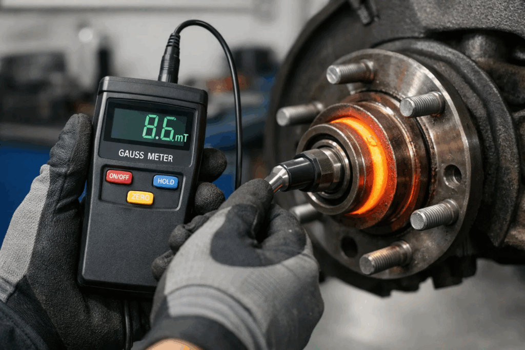
The Problem: Steel components become magnetised during induction heating as a natural consequence of the alternating electromagnetic field. When the heating cycle ends and the component cools, residual magnetism remains — and in automotive contexts, this is far more damaging than most technicians realise.
Why It Happens: Demagnetisation is often skipped because the magnetism is invisible, the process seems optional, and the short-term consequences are not immediately obvious.
What Goes Wrong:
The Fix:
Key Takeaway: Demagnetisation is not optional — it is a mandatory final step in every induction heating cycle on automotive components. Skipping it is a liability that compounds invisibly until the next service interval.
The Problem: Induction heating works by inducing eddy currents within conductive materials. If the workpiece has pre-existing cracks, porosity, or hidden surface defects, the concentrated electromagnetic field at those discontinuities generates extreme local heating — often enough to propagate the crack or cause thermal fracture.
Why It Happens: In a busy workshop, components are assumed to be serviceable until they are visually inspected — but many subsurface defects are invisible to the naked eye. A cracked inner bearing race, for example, looks perfectly normal before heating.
What Goes Wrong:
The Fix:
Key Takeaway: Induction heating amplifies whatever condition the component is already in. A good component heats correctly. A cracked or corroded component heats catastrophically. Inspect before you heat — every time.
The Problem: When induction heating is used on or near electric motor components — starter motors, alternators, EV drive motors, or traction motor bearings — the thermal event can affect winding insulation integrity, particularly if heat creep occurs into adjacent insulation materials. Most automotive workshops perform the mechanical assembly perfectly and never check whether the motor’s electrical integrity survived the process.
Why It Happens: Electrical verification requires specialist test equipment that many automotive workshops do not stock. The assumption is that if the bearing seats correctly and the motor spins, everything is fine. It is not a safe assumption.
What Goes Wrong:
The Fix:
After any induction heating job on or adjacent to electric motor components, perform a structured electrical verification sequence:
Explore more about winding fault detection in our guides on motor winding failure signs and how to test motor windings.
Key Takeaway: Mechanical success after induction heating does not guarantee electrical safety. On any job touching motor components, surge testing and insulation resistance checks are the only way to confirm the motor is truly service-ready.
Not all induction heaters are built for the demands of automotive maintenance. Here is what to look for:
Vivid’s quick-heaters prevent uneven heating through their precision power regulation and multi-coil compatibility — a critical capability for shops handling a diverse vehicle fleet.
For a broader comparison of what makes an industrial-grade heater suitable for demanding environments, explore our guide on best induction heater for industrial applications.
For automotive workshops seeking to understand how frequency selection impacts heating performance across different component sizes, our low vs high frequency induction heating guide is essential reading. Similarly, shops moving toward EV servicing will find the smart induction heating precision efficiency industry article directly relevant to digital-era heating applications.
Most automotive wheel bearings should be heated to 80–110°C (176–230°F). This provides sufficient expansion for clean assembly without approaching the 120°C threshold where microstructural damage begins. Always verify with a contact thermometer, not just the heater’s timer.
Yes, but with significant caution. Aluminium has much lower thermal conductivity thresholds and expands rapidly. Most aluminium alloy automotive housings should not exceed 150°C, and the heating cycle must be carefully controlled. Use a heater with precise temperature regulation and a fine-pitch coil.
Visual signs include discolouration (blue or straw hues on the steel surface), reduced bearing clearance after cooling, or a rough feel when the bearing is rotated by hand. Metallurgically, overheated bearings exhibit reduced surface hardness detectable by a Vickers hardness test. Electrically, a post-heat surge test can identify if insulation in adjacent windings has been compromised.
For non-magnetic circuit applications (e.g., purely mechanical bearing fits in non-electronic vehicle systems), low residual magnetism may be acceptable. However, for any component near ABS sensors, magnetic encoders, EV resolvers, or engine management sensors, demagnetisation is mandatory.
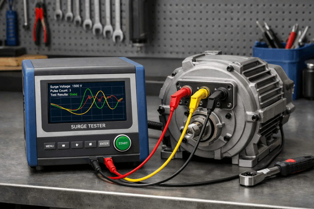
A Megger (insulation resistance) test applies DC voltage and measures bulk insulation resistance — it detects gross insulation breakdown. A surge test applies high-voltage impulse pulses and compares waveforms between windings — it detects inter-turn shorts that a Megger cannot find. Both are complementary. Review our dedicated guide on the difference between megger and surge test for windings for a detailed technical comparison.
Absolutely — and it is one of its most powerful automotive applications. Induction heating expands the seized fastener faster than the surrounding material, breaking the corrosion bond without damaging threads or surrounding castings. See our step-by-step guide on how to use induction heating for bolt removal for the correct technique.
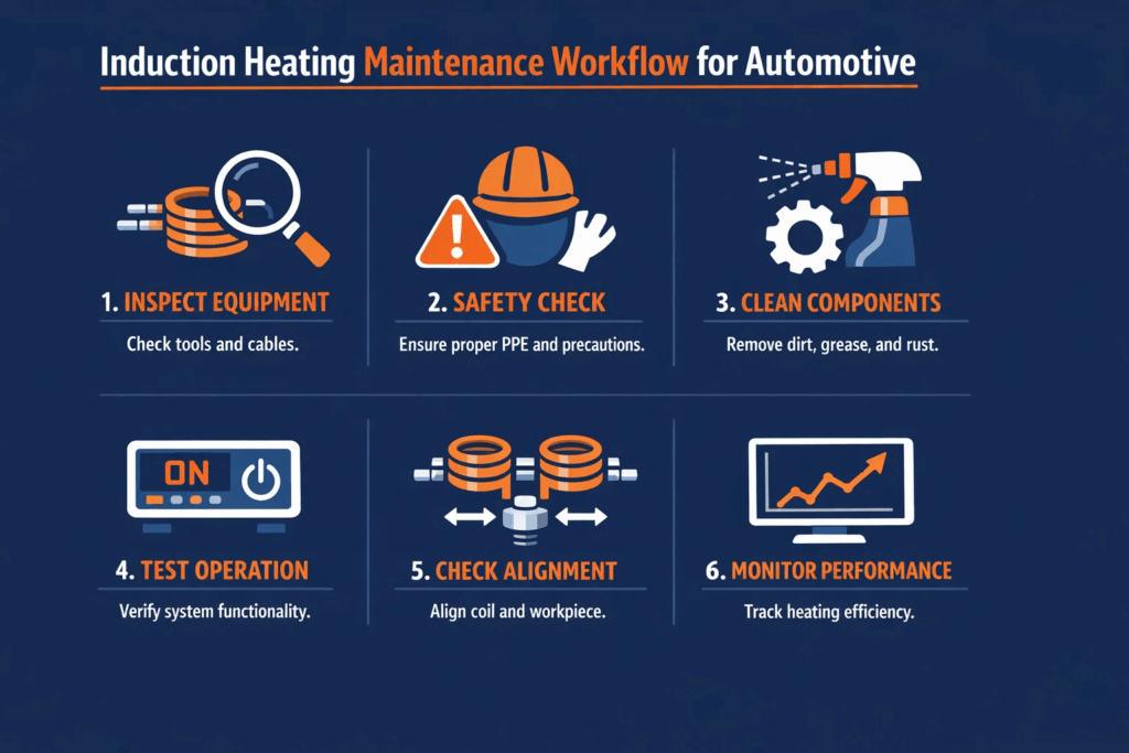
Induction heating is one of the most powerful tools available to modern automotive maintenance professionals — but it demands precision, preparation, and a structured post-process verification routine. The five induction heater mistakes in automotive maintenance covered in this guide — wrong coil selection, temperature overrun, skipped demagnetisation, no pre-heat inspection, and absent electrical verification — are preventable in every case when the right equipment and workflow are in place.
For automotive workshops ready to adopt professional-grade induction heating, Vivid Metrawatt Global offers a comprehensive range of heaters — from compact 22 kW units for passenger vehicle work to powerful 44 kW models for commercial and EV fleet maintenance. When paired with Vivid’s digital surge testing equipment, your workshop can deliver a complete, documented, electrically verified maintenance workflow that protects both the vehicle and your reputation.
Vivid Metrawatt Global engineers induction heating solutions built specifically for precision industrial and automotive maintenance — with closed-loop temperature control, integrated degaussing, and the power density to handle everything from delicate bearing installations to heavy-duty gear hub shrink fits.
Stop risking premature component failure. Start heating with confidence.
👉 Explore Vivid’s Industrial Induction Heater Range — 22kW to 44kW models available for workshops, fleet maintenance centres, and OEM service teams.