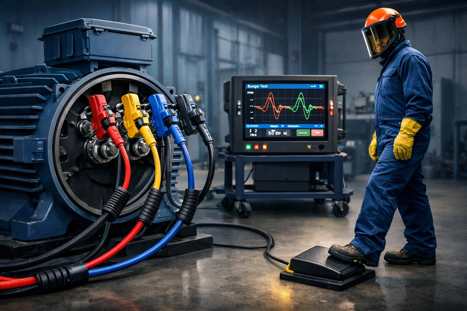
Manual surge testing requires operators to constantly reach for control buttons while simultaneously positioning test leads and observing waveforms, creating safety risks and reducing testing efficiency. Divided attention between manual controls and critical visual analysis leads to missed fault indications, improper lead positioning, and potential electrical hazards when hands remain near energized terminals. Footswitch-operated surge testers enable hands-free control, allowing technicians to maintain safe distance from test points, optimize lead placement, and focus entirely on waveform analysis improving both safety and diagnostic accuracy.
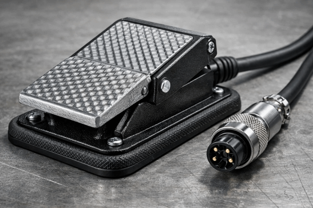
A footswitch is a floor-mounted control device that activates surge testing operations through foot pressure, eliminating the need for manual button operation. Connected to digital surge testers via cable, the footswitch serves as a remote trigger enabling completely hands-free test initiation and control.
Key footswitch characteristics:
The footswitch concept emerged from industrial quality control environments where technicians needed both hands free for component handling, lead positioning, and visual inspection during high-voltage testing. Originally developed for automotive and aerospace manufacturing, footswitch technology has become standard in modern surge testing equipment.
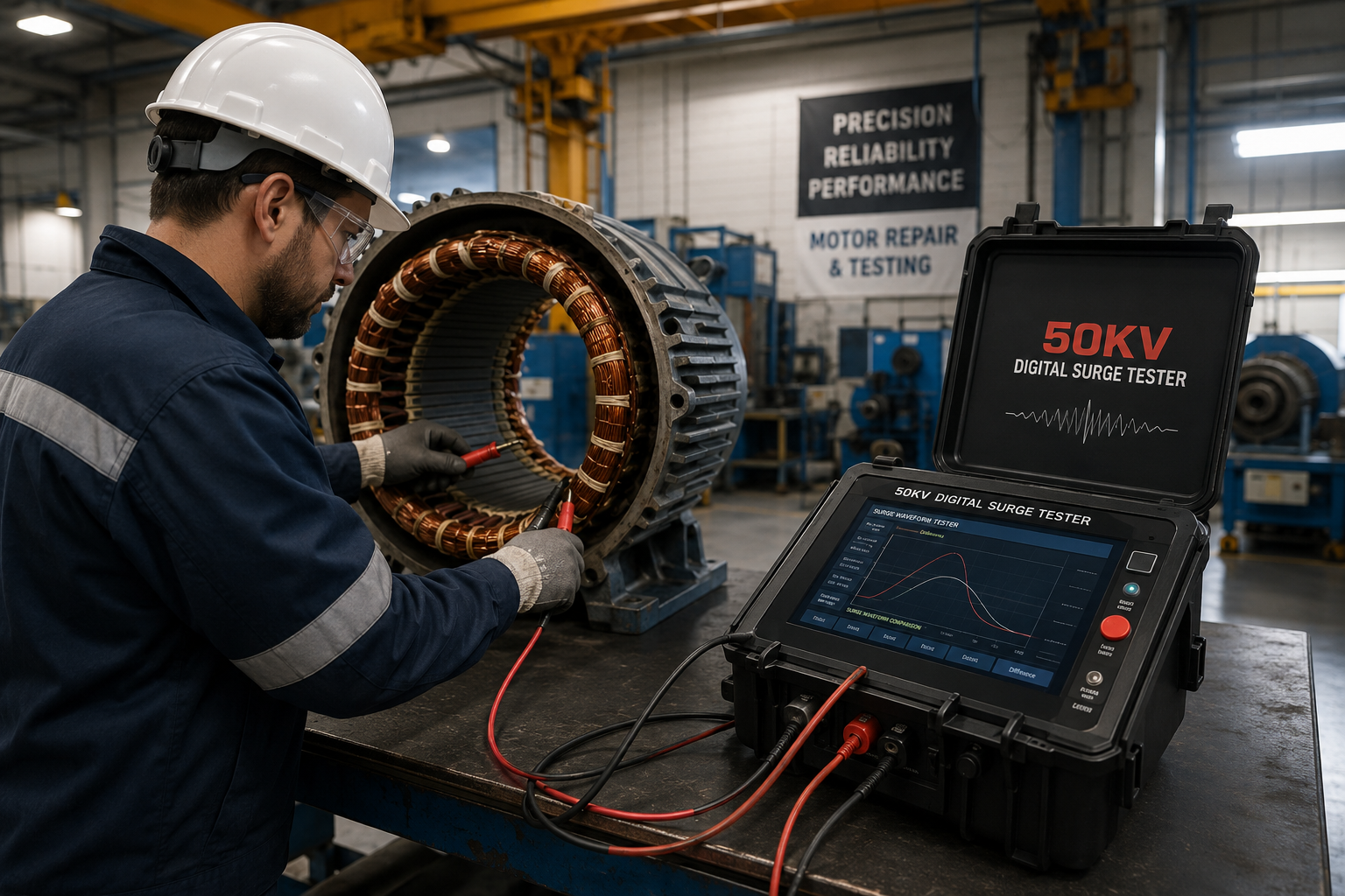
Why footswitches matter for surge testing: Motor winding testing requires precise lead placement on specific terminals while simultaneously monitoring oscilloscope displays for characteristic fault signatures. Manual button operation forces technicians to repeatedly move hands between test leads and control panel—introducing positioning errors, extending test time, and creating safety hazards when hands approach energized terminals.
Footswitch control solves these problems by relocating the activation mechanism to foot-operated controls, freeing hands for critical positioning and adjustment tasks while maintaining complete surge test control.
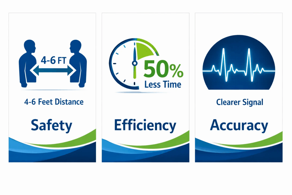
Implementing footswitch-controlled surge testing delivers measurable improvements across safety, efficiency, and diagnostic accuracy:
Distance from high voltage: With footswitch control, technicians position test leads, then step back to safe distances before initiating surge pulses. This separation provides crucial protection against:
Two-hand lead positioning: Footswitch operation enables simultaneous two-hand lead control during testing. Operators securely hold both test probes, preventing lead displacement or slippage that could create dangerous ground paths or short circuits.
Zero Start Lock compatibility: Modern surge testers incorporating zero start lock features require grounded test leads before enabling high voltage. Footswitch control complements this safety system—operators cannot energize test circuits unless leads are properly connected and grounded.
Reduced cycle time: Eliminating the hand motion between lead positioning and button pressing reduces per-test time by 3-5 seconds. For facilities testing hundreds of motors weekly, this efficiency gain translates to hours of reclaimed productivity monthly.
Continuous workflow: During bar-to-bar armature testing requiring sequential measurements at each commutator segment, footswitch operation enables smooth continuous rotation. The operator turns the armature with both hands while triggering surge pulses via foot control, completing comprehensive testing in half the time manual operation requires.
Multi-unit comparison testing: When comparing three-phase motor winding tests across all phase combinations (L1-L2, L2-L3, L3-L1), footswitch control streamlines lead repositioning. Operators move test leads to new terminals using both hands, then immediately trigger the next test without reaching for control buttons.
Focused visual analysis: Hands-free control allows uninterrupted attention on waveform displays during surge application. Technicians can concentrate on subtle waveform characteristics—frequency shifts, amplitude variations, damping differences—without dividing attention between display monitoring and button operation.
Optimal lead positioning: Both hands free for lead manipulation enables precise probe placement on exact terminal points. This accuracy matters particularly when testing small motors with closely-spaced terminals or armature testing where commutator segment contact requires careful positioning.
Real-time adjustment capability: If initial waveforms show marginal indications requiring lead repositioning for confirmation, operators can immediately adjust probe placement while maintaining foot on the switch, retriggering tests without hand repositioning delays.
For manufacturers implementing comprehensive quality control programs, footswitch operation integrates seamlessly with automated motor testing systems, supporting high-throughput production testing requirements.
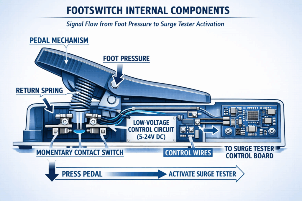
Understanding footswitch electrical and mechanical operation helps technicians maximize effectiveness while troubleshooting potential problems:
Modern surge tester footswitches employ simple normally-open contact closure mechanisms providing safe, reliable control:
Basic circuit operation: The footswitch contains a momentary contact switch (typically SPST – Single Pole Single Throw) connected in series with the surge tester’s internal test initiation circuit. When foot pressure closes the switch contacts, the circuit completes, sending an activation signal to the surge generator control board.
Low-voltage control circuit: Footswitches operate on low-voltage control circuits (typically 5-24V DC) completely isolated from high-voltage surge output. This isolation ensures operator safety—even if footswitch internal wiring shorts or contacts arc, the low voltage presents no shock hazard.
Momentary operation: Surge tester footswitches use momentary contact design rather than latching switches. The test circuit energizes only while foot pressure maintains contact closure. Releasing pressure immediately opens the circuit, terminating surge generation. This fail-safe design prevents unintended test continuation if operators need to quickly abort testing.
Connection types: Footswitches connect to surge testers through various interface methods:
Heavy-duty housing: Quality footswitches feature metal or reinforced polymer housings protecting internal components from:
Ergonomic pedal design: The actuating pedal provides large surface area (typically 3-5 inches square) accommodating various footwear from safety boots to athletic shoes. Textured or ribbed pedal surfaces improve grip, preventing foot slippage during activation.
Non-slip base: Rubber feet or complete rubber base pads prevent footswitch movement during operation. Adequate friction between footswitch and floor maintains stable positioning even during repeated rapid activation cycles.
Spring return mechanism: Internal spring automatically returns the pedal to raised position when foot pressure releases. Spring tension is calibrated to provide tactile feedback confirming activation while requiring minimal force preventing operator fatigue during extended testing sessions.
Test mode selection: Some advanced surge testers program different footswitch behaviors for various testing modes:
Interlock systems: Footswitch operation integrates with surge tester safety interlocks:
Understanding these operational principles helps technicians performing surge tester troubleshooting diagnose footswitch-related problems and maintain reliable operation.
Proper footswitch installation and positioning optimizes ergonomics, safety, and operational efficiency:
Step 1: Verify compatibility – Confirm your surge tester model supports footswitch operation. Most modern digital surge testers include footswitch jacks, but older analog models may require modification.
Step 2: Inspect footswitch cable – Before connection, visually examine the entire cable length for:
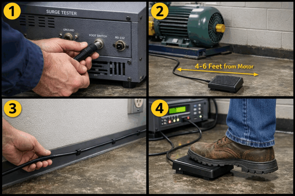
Step 3: Connect to surge tester – Locate the footswitch input jack (typically labeled “FOOTSWITCH,” “REMOTE,” or “EXT TRIGGER”) on the surge tester rear panel. Firmly insert the footswitch cable connector until it seats completely. Some connectors include locking collars—rotate clockwise to secure.
Step 4: Verify operation – Before testing on actual motors, confirm footswitch functionality:
Distance from test point: Position footswitch 4-6 feet from the test workstation. This distance:
Operator stance consideration: Place footswitch slightly to the dominant foot side. Right-handed operators typically position footswitch toward right foot, while maintaining centered body position for symmetrical reach to left and right motor terminals.
Surface verification: Ensure footswitch rests on stable, level surface. Avoid:
Cable management: Route footswitch cable to prevent:
Test lead staging: With footswitch control freeing hands, organize test leads for optimal accessibility:
Display positioning: Adjust surge tester display screens to comfortable viewing height and angle. Optimal positioning places the center of the display at operator eye level when standing in normal testing position with footswitch beneath the dominant foot.
Component staging: Arrange motors or coils for testing in logical sequence within arm’s reach. This organization minimizes movement between tests, maximizing the efficiency benefits footswitch operation provides.
Mastering footswitch technique ensures consistent, accurate testing while preventing operator fatigue:
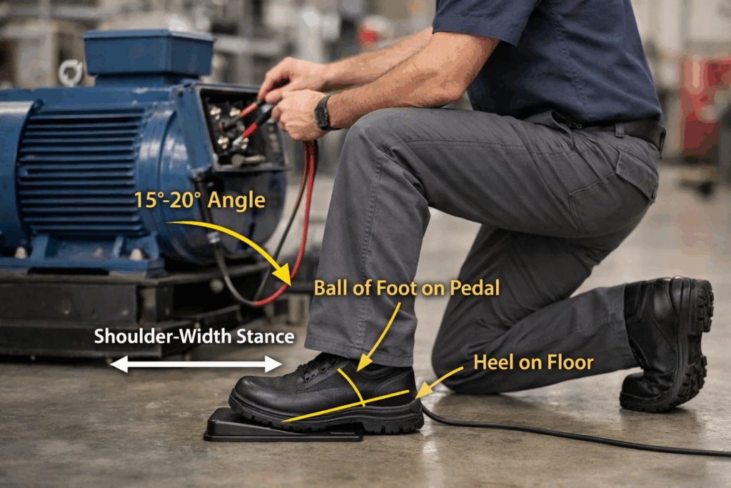
Stance: Stand with feet shoulder-width apart, weight distributed evenly. Position dominant foot (typically right) directly above footswitch pedal with ball of foot over pedal center. Non-dominant foot remains planted, providing stable base.
Foot placement: Rest ball of foot on pedal surface without applying pressure. Heel remains on floor providing leverage and stability. This position enables quick, controlled activation using ankle flexion rather than leg movement.
Activation motion: Press pedal with smooth, controlled downward ankle flexion. Avoid:
Timing coordination: Develop rhythm coordinating foot activation with test preparation:
Rapid repetition testing: For bar-to-bar armature testing requiring measurements at each commutator segment:
Variable pressure control: Some surge testers offer pressure-sensitive footswitch triggering:
Simultaneous dual-task operation: For complex testing procedures requiring winding manipulation during surge application:
Fatigue prevention: During extended testing sessions (2+ hours):
Body mechanics: Maintain proper posture during footswitch operation:
Proper technique becomes especially important during high-volume motor testing in manufacturing quality control environments where technicians may conduct hundreds of tests daily.
Footswitch operation provides multiple safety benefits beyond simple convenience:
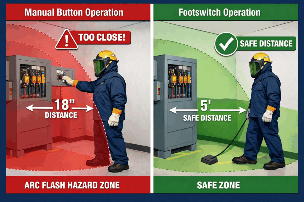
Arc flash mitigation: When surge testing identifies turn-to-turn shorts, the insulation breakdown can produce visible arcing. With footswitch control, operators stand 4-6 feet from test points—beyond typical arc flash zones. Manual button operation often positions operators within 18-24 inches of energized terminals, increasing exposure risk.
Secondary voltage protection: High-voltage surge pulses can induce dangerous voltages in adjacent conductors, nearby tools, or motor frames. Footswitch operation maintains operator distance from these hazards during the critical moment of surge application.
Accidental contact prevention: The most common surge testing injury involves accidental contact with energized test leads while reaching for control buttons. Footswitch control eliminates this hand motion, removing the associated hazard entirely.
Secure probe positioning: Simultaneous two-hand lead control prevents probe displacement during surge application. A dislodged probe can create:
Ground clamp verification: Many surge testing procedures require temporary ground connections to motor frames or terminal enclosures. With hands free, operators can verify secure ground clamp attachment immediately before triggering surge, then maintain visual confirmation throughout testing.
Emergency disconnect capability: If unexpected motor movement, smoke, or other hazards occur during testing, operators with both hands on test leads can immediately disconnect probes while simultaneously releasing footswitch pressure terminating surge generation.
Reduced task overload: Operating manual buttons while holding test leads, monitoring displays, and mentally processing waveform information creates cognitive overload. This divided attention increases error probability. Footswitch operation removes manual button operation from the mental task list, allowing greater focus on safety-critical observation and analysis.
Consistent protocol adherence: Safety procedures become more reliable when physically simpler to execute. The footswitch testing protocol—position leads, step back, observe, then trigger—establishes consistent safe habits more easily than protocols requiring operators to repeatedly approach and retreat from test points.
For comprehensive safety understanding, review surge testing safety guidelines covering all aspects of high-voltage motor testing.
Footswitch control provides particular advantages in specific surge testing scenarios:
The challenge: DC armature testing requires surge measurements between each adjacent commutator segment pair. A typical automotive starter armature might have 20+ segments, requiring 20+ individual measurements while manually rotating the armature between tests.
Footswitch advantage: Operators grasp the armature shaft with both hands, rotating smoothly from segment to segment. The footswitch triggers surge pulses at each position without hand repositioning. Testing time reduces by 50% compared to manual button operation requiring hand transfer between armature and button for each measurement.
Technique refinement: Develop rhythm coordinating rotation angle with footswitch timing. Experienced technicians achieve smooth, metronomic testing cadence—rotate, press, observe, release, rotate—completing comprehensive armature evaluation in 2-3 minutes.
The challenge: High-voltage motors with widely-spaced terminals require test leads approaching or exceeding maximum length. Lead weight and stiffness demands two-hand positioning for secure connection.
Footswitch advantage: With both hands securing heavy test leads to motor terminals, footswitch control eliminates the impossible task of simultaneously holding leads and pressing buttons. For motors requiring ladder access or awkward positioning, footswitch on the floor below provides comfortable control while technicians focus on maintaining safe lead contact.
The challenge: Manufacturing environments testing sequential production units demand maximum throughput. Every second of test cycle time directly impacts production capacity and labor costs.
Footswitch advantage: Operators establish efficient motion economy: While one unit undergoes surge testing, hands prepare the next unit (removing shipping covers, identifying terminals, staging leads). The instant current test completes, operator moves leads to next unit and triggers test via footswitch without breaking workflow rhythm.
Documented efficiency gains: Automotive motor manufacturers report 30-40% throughput improvement implementing footswitch surge testing versus manual button operation, translating to significant productivity gains at production volumes of thousands of motors monthly.
The challenge: Field testing environments—plant floors, equipment rooms, outdoor installations—often lack convenient surge tester placement. Testers may sit on rolling carts, floor level, or temporary surfaces while motors under test are mounted overhead, below grade, or in restricted access areas.
Footswitch advantage: Long footswitch cable (6-10 feet) allows tester placement wherever convenient while operator positions near motor terminals. Technicians can focus on accessing difficult test points using both hands while maintaining complete surge testing control via footswitch.
For field testing applications, understanding difference between surge and impulse testing helps technicians select appropriate equipment and techniques for specific diagnostic scenarios.
Direct comparison clarifies when footswitch operation provides measurable advantages:
| Factor | Footswitch Control | Manual Button | Advantage |
|---|---|---|---|
| Operator position | 4-6 feet from test point | 12-24 inches from test point | Footswitch (safety) |
| Hands available | Both hands free | One hand on button | Footswitch |
| Lead positioning | Two-hand secure control | One-hand holding | Footswitch |
| Display observation | Continuous focus possible | Divided attention | Footswitch |
| Test cycle time | 3-5 seconds per test | 5-8 seconds per test | Footswitch |
| Armature testing | Continuous rotation/test | Repeated hand transfers | Footswitch |
| Learning curve | 15-30 minutes familiarization | Immediate intuitive use | Manual button |
| Setup complexity | Additional cable/positioning | Ready to use | Manual button |
| Maintenance | Additional component | Fewer components | Manual button |
When manual buttons make sense:
When footswitches provide clear advantage:
For organizations evaluating testing equipment, consider selecting appropriate surge testing equipment based on testing volume, motor types, and safety requirements.
Recognizing typical errors helps technicians maximize footswitch effectiveness:
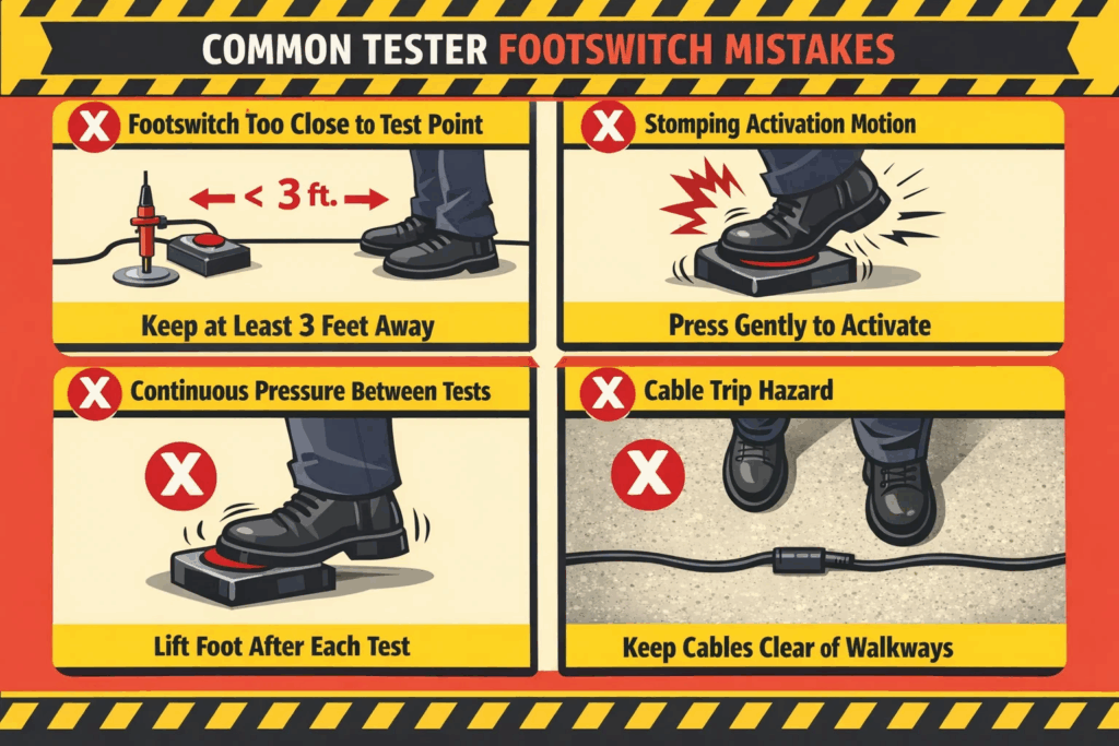
Mistake #1: Footswitch too close to test point
Placing footswitch within 2-3 feet of motors under test defeats the safety purpose. Operators lean forward reaching terminals, compromising the distance-based protection footswitch control provides.
Solution: Position footswitch minimum 4-6 feet from test points. If this requires slightly longer reach to motor terminals, accept the trade-off—safety benefits outweigh minor accessibility reduction.
Mistake #2: Unstable footswitch placement
Setting footswitch on uneven floors, slopes, or unstable surfaces creates movement during operation. The footswitch shifts position, requiring operator adjustment that disrupts testing rhythm and potentially causes missed activations.
Solution: Ensure level, stable floor surface. If floor conditions are suboptimal, place footswitch on small stable platform or rubber mat providing consistent positioning.
Mistake #3: Cable trip hazards
Routing footswitch cable across walkways or equipment traffic paths creates tripping hazards and cable damage risk from rolling equipment or dropped tools.
Solution: Route cable along walls, under work benches, or use cable covers if workspace paths cannot be avoided. Consider overhead cable suspension for permanent test stations.
Mistake #4: Stomping activation
Aggressively stomping footswitch pedal creates:
Solution: Use controlled ankle flexion applying only sufficient pressure for contact closure. Quality footswitches require minimal force (typically 5-10 pounds pressure).
Mistake #5: Continuous pressure maintenance
Holding footswitch pressed between tests keeps surge circuits energized unnecessarily, increasing safety risk and potentially causing unintended surge generation.
Solution: Release footswitch immediately after each test. Maintain foot in ready position above pedal but without contact. Press only when prepared to conduct next test.
Mistake #6: Divided attention during activation
Pressing footswitch while simultaneously moving test leads, adjusting settings, or performing other tasks diverts attention from critical surge observation.
Solution: Complete all test preparation (lead positioning, voltage selection, display setup) before footswitch activation. Once preparation is complete, focus entirely on display observation, then press footswitch initiating surge.
Mistake #7: Neglecting footswitch inspection
Footswitches endure harsh floor environments—contamination, impacts, temperature extremes. Ignoring condition assessment leads to unexpected failures during critical testing.
Solution: Weekly visual inspection checking:
Mistake #8: Improper cleaning
Using solvents, pressure washers, or abrasive cleaning methods damages footswitch electronics, seals, and surface finishes.
Solution: Clean footswitch using damp cloth with mild detergent. Avoid moisture entry into connector or housing seams. Immediately dry all surfaces after cleaning.
Learning from these common mistakes while understanding maintenance of surge testing equipment ensures reliable long-term footswitch operation.
Proper maintenance extends footswitch service life and maintains reliable operation:
Daily checks (high-use environments):
Weekly inspection:
Monthly maintenance:
Surface cleaning:
Connector maintenance:
When not in use:
Long-term storage (>30 days):
Replace footswitch when experiencing:
Replacement selection: When purchasing replacement footswitches, verify:
Ready to enhance your surge testing operations? Contact Vivid Metrawatt Global to discuss surge testing equipment with integrated footswitch control for maximum safety and efficiency.
No, footswitches must be electrically compatible with your specific surge tester model. Surge testers use various control circuit configurations—some employ normally-open contacts, others normally-closed, and voltage/current requirements vary. Using incompatible footswitches can damage surge tester control circuits or create safety hazards. Always use manufacturer-specified footswitches or verify electrical compatibility before connecting aftermarket alternatives.
Disconnect the footswitch from the surge tester and use a multimeter set to continuity/resistance mode. Touch probes to footswitch connector pins. With pedal released, meter should show infinite resistance (open circuit). Press pedal—meter should show near-zero resistance (closed circuit). If readings don’t change with pedal operation, footswitch contacts have failed. Also test across all connector pin combinations to verify no unintended shorts exist.
Cable extension is possible but requires careful consideration. Long cables introduce capacitance and inductance potentially interfering with control signals. For extensions under 10 feet, use shielded cable matching original gauge. Avoid coiling excess cable—this creates inductance. For extensions exceeding 10 feet, consult surge tester manufacturer—active signal amplification may be necessary. Never splice cables using wire nuts or electrical tape; use proper connectors maintaining shielding continuity.
Cable damage requires immediate attention as exposed conductors create shock hazards and could cause surge tester malfunction. Minor insulation abrasion can be repaired using heat shrink tubing providing wire isolation isn’t compromised. However, cables with cut, crushed, or deeply abraded insulation should be replaced entirely. Temporary repairs with electrical tape are insufficient for industrial surge testing environments. Replacement cables must match original specifications—consult manufacturer for proper replacement parts.
Effective training includes: (1) Safety overview explaining distance-based protection benefits, (2) Proper stance and foot positioning demonstration, (3) Practice activation without surge tester energized, (4) Supervised initial testing on low-voltage calibration loads, (5) Progression to actual motor testing under supervision, (6) Independent operation after demonstrating consistent proper technique. Most operators become proficient within 30-60 minutes of practice. Emphasize smooth controlled activation rather than aggressive stomping, and reinforce the safety principle of complete test preparation before footswitch activation.
Footswitch-controlled surge testing represents a simple yet transformative improvement in motor diagnostic operations, delivering simultaneous gains in safety, efficiency, and diagnostic accuracy. By relocating test activation from hand-operated buttons to foot-controlled switches, the technology enables operators to maintain optimal distance from energized test points while dedicating both hands to critical lead positioning and waveform observation tasks.
The safety benefits prove particularly compelling—reduced arc flash exposure, eliminated accidental contact risk, and consistent two-hand lead control protecting technicians from the primary hazards associated with high-voltage motor testing. These advantages become even more significant in production testing environments where technicians conduct hundreds of tests daily, with cumulative exposure risk proportional to test volume.
Efficiency improvements, though measured in seconds per test, aggregate to substantial productivity gains. The 30-40% throughput improvement documented in high-volume manufacturing demonstrates footswitch operation’s measurable business value beyond safety considerations. For facilities testing significant motor populations, these efficiency gains provide rapid return on minimal footswitch investment.
Implementation requires minimal learning curve—most operators master proper footswitch technique within an hour of initial training. The investment remains modest (typically $50-150 for quality footswitches) relative to comprehensive surge testing equipment costs, making footswitch control accessible to organizations of any size.
For maintenance professionals, motor manufacturers, and quality control teams committed to operational excellence, footswitch-controlled surge testing delivers measurable improvements making it an essential standard practice rather than optional enhancement. The combination of safety protection, efficiency improvement, and enhanced diagnostic capability establishes footswitch operation as best practice in modern motor testing programs.
Explore Vivid Metrawatt Global’s complete range of footswitch-equipped surge testing solutions—from entry-level LCD-based testers to advanced touchscreen systems with automated analysis—designed for safe, efficient, and precise motor diagnostics across all industrial applications.