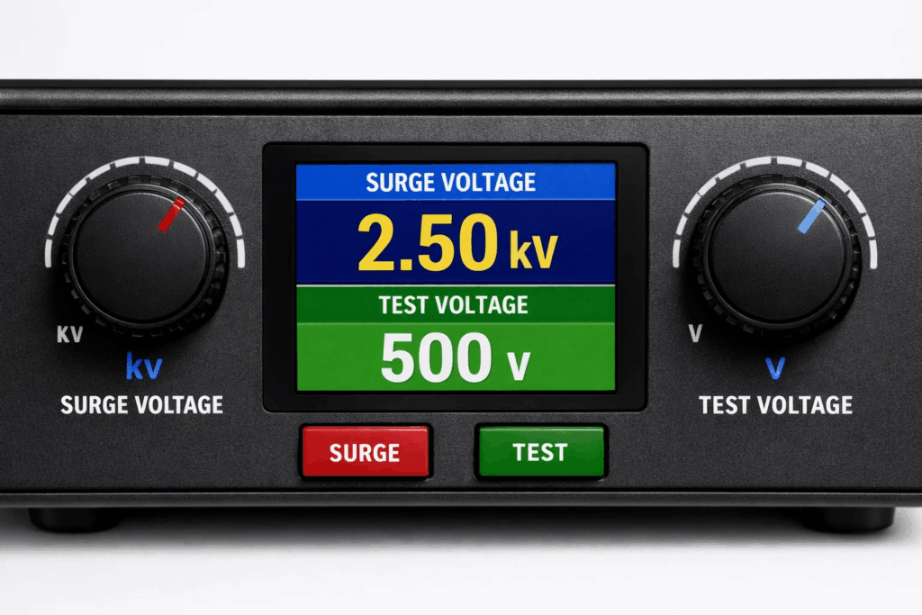
When technicians first encounter a digital surge tester, one of the most common sources of confusion is the distinction between “surge voltage” and “test voltage” — terms that appear on the instrument panel and in the test procedure, often without sufficient explanation.
Using the wrong voltage level for a test can produce misleading results, fail to detect real faults, or — in the worst case — damage the very insulation you are trying to evaluate. This guide explains both terms precisely, shows how they interact, and gives you a clear framework for selecting the correct settings for your specific application.
For a foundation in surge tester operation: What Is a Surge Tester? — Complete Guide
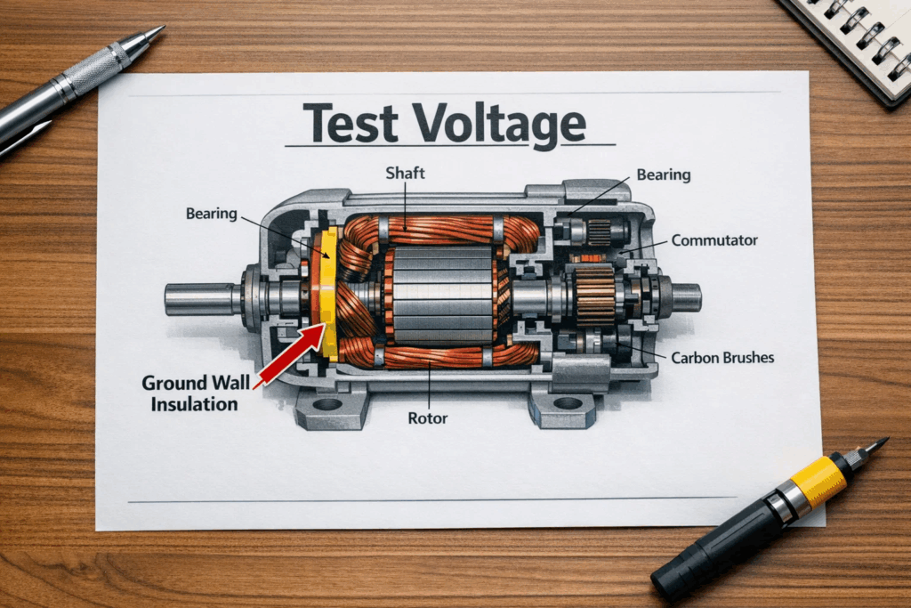
Test voltage — sometimes called hipot voltage or dielectric withstand voltage — is the sustained DC or AC voltage applied between a winding conductor and the motor frame (ground) during a hipot (high-potential) test. Its purpose is to verify that the ground wall insulation can withstand overvoltage conditions without breaking down.
Key Characteristics of Test Voltage
Full hipot testing guide: What Is Hipot Testing in a Digital Surge Tester?
AC vs DC hipot — which is appropriate? AC Hipot vs DC Hipot Testing — Full Comparison
Surge voltage — also called impulse voltage — is the peak voltage of the rapid, high-voltage pulse that the surge tester fires into the winding to perform an impulse winding test. Unlike test voltage, surge voltage is not sustained: it lasts only microseconds before the circuit begins to oscillate at its natural resonant frequency.
Key Characteristics of Surge Voltage
Critical Distinction:
Surge voltage stresses inter-turn insulation and produces a waveform for comparison. Test voltage stresses ground wall insulation and produces a leakage current for measurement. They test fundamentally different insulation systems within the same motor.
How surge generators produce the impulse: How Surge Generators Work
Explore the difference between impulse and surge voltage testing: Difference Between Impulse and Surge Voltage Testing
| Parameter | Surge Voltage | Test Voltage (Hipot) |
| Duration | Microseconds (pulse) | Sustained (typically 60 seconds) |
| Voltage Type | Impulse / DC pulse | DC or AC sustained |
| Target | Turn-to-turn insulation | Ground wall insulation |
| Analysis Method | Waveform comparison (EAR, shape) | Leakage current or IR measurement |
| Standard Reference | IEEE 522, IEC 60034-15 | IEEE 43, IEC 60034-1 |
| Motor Impact | Very low if correctly set | Higher cumulative stress — limit frequency |
| Result Output | Pass/Fail + waveform overlay | Pass/Fail + leakage current value |
Selecting the correct surge voltage is one of the most important — and most commonly misunderstood — steps in performing an impulse winding test. Too low, and you will not stress the insulation enough to reveal weaknesses. Too high, and you risk damaging healthy insulation.
IEEE 522 Surge Voltage Guidelines
Example:
For a 400V rated motor: new motor surge voltage = (2 × 400) + 1000 = 1800V. For an in-service test: 1.75 × 400 = 700V minimum, typically 1000–1200V in practice.
Practical Surge Voltage Selection Table
| Motor Rated Voltage | New Motor / Post-Rewind | In-Service Test |
| Up to 230V | ≤ 1700V | ≤ 1000V |
| 400V–480V | 1800V–2000V | 1200V–1500V |
| 1000V–1500V | 3000V–4000V | 2000V–2500V |
| 3300V–4000V | 7600V–9000V | 5000V–6000V |
| 6000V–6600V | 13000V–14200V | 9000V–10000V |
Note: Always consult IEEE 522, IEC 60034-15, or OEM specifications for your specific application.
The hipot test voltage is calculated differently from surge voltage, because it tests a different insulation system: the wall between the conductor and the motor frame.
IEEE 43 and IEC 60034-1 Hipot Voltage Guidelines
Important Safety Note:
Never exceed the OEM-specified hipot voltage. Once the dielectric withstand voltage is specified for a motor at manufacture, subsequent tests should use reduced levels. Repeated high-voltage hipot testing will gradually accumulate damage in the ground wall insulation.
What is high-voltage testing? What Is a High Voltage Test?
Understanding how waveforms change with voltage level helps you interpret results more accurately.
At Correct Test Voltage
The waveform is clear, well-defined, and steady. Phase-to-phase comparison shows near-identical waveforms for a healthy motor. The EAR value is minimal.
At Too Low a Voltage
Marginal insulation weaknesses are not stressed enough to produce detectable waveform asymmetry. The test appears to pass, but a real fault is present. This is the most dangerous outcome: a false negative.
At Too High a Voltage
Excessive voltage may produce partial discharge within the winding, visible as waveform noise or instability — even in a healthy motor. This can lead to false positives, and repeated over-voltage testing will gradually degrade the insulation.
How to read and analyse waveforms: Waveform Analysis in Surge Testing
Understanding Error Area Ratio: What Is Error Area Ratio (EAR)?
Avoid common testing errors: Troubleshooting Common Surge Tester Errors
General electrical testing troubleshooting: Troubleshooting Common Electrical Testing Errors
Vivid Metrawatt’s digital surge tester range covers every voltage class from small fractional-HP motors to large high-voltage machines. Each instrument provides precisely adjustable surge and hipot voltage settings to match IEEE and IEC requirements.
For motors rated up to 230V–480V: 5kV–6kV Digital Surge Tester with DC HiPot
For medium-voltage motors (1kV–4kV rated): 10kV–15kV Digital Surge Tester with HiPot
For high-voltage motors (6kV–10kV rated): 25kV–40kV Digital Surge Tester
For the most demanding large HV machines: 50kV Digital Surge Tester
Combined surge and hipot in one instrument: 25kV–40kV Digital Surge Tester with DC HiPot
For armature and small motor testing: 3kV Digital Armature Surge Tester
Need help choosing the right tester? Choosing the Right Surge Tester for Your Needs
Surge voltage is the peak voltage of the rapid impulse pulse applied to a winding during a surge test — it stresses turn-to-turn insulation and produces a waveform for comparison. Test voltage (hipot voltage) is the sustained DC or AC voltage applied between the winding and ground during a hipot test — it verifies ground wall insulation integrity. They test completely different insulation systems.
Surge voltage is an impulse — its job is to create a rapidly rising voltage wave that non-uniformly distributes across winding turns, stressing inter-turn insulation. The oscillating waveform it produces is the diagnostic signal. Test voltage is sustained because ground wall insulation must demonstrate it can withstand elevated voltage for a meaningful duration without breaking down.
IEEE 522 recommends: for new or rewound motors, surge voltage = 2 × rated voltage + 1000V. For in-service motors, use 1.5–1.75 × rated voltage. For a 400V rated motor, the new motor surge voltage would be (2 × 400) + 1000 = 1800V.
IEEE 43 and IEC 60034-1 recommend: for new motors, test voltage = 2 × rated voltage + 1000V (AC RMS). For in-service motors, reduce to 1.25–1.5 × rated voltage + 1000V. Repeat hipot testing should never exceed 75% of the original test voltage.
Not necessarily — although the formula is similar for new motors, the two voltage values serve different purposes and are applied in different test modes on the instrument. Always set surge voltage in surge test mode and hipot voltage in hipot test mode, following the correct standard for each.
If surge voltage is set below the recommended level, inter-turn insulation weaknesses will not be sufficiently stressed to produce detectable waveform asymmetry. The test will appear to pass even though a real fault is present — a dangerous false negative outcome.
Excessive surge voltage can induce partial discharge within the winding — producing waveform noise that mimics a fault in a healthy motor (false positive). More seriously, repeated over-voltage testing will gradually damage healthy insulation, accelerating its degradation.
AC hipot is more representative of the operational electrical stress a motor experiences. DC hipot is gentler on the insulation and can be more informative for trending insulation condition over time. IEEE 43 permits both; the choice depends on application, motor voltage class, and available instrumentation.
Yes — most professional-grade digital surge testers, including those in the Vivid Metrawatt range, integrate both surge (impulse) testing and DC hipot testing in a single instrument. This allows a complete winding and ground insulation test protocol without switching between separate instruments.
At the correct surge voltage, a healthy motor produces a clear, stable, well-defined damped sinusoidal waveform. All three phases overlay almost perfectly. The EAR value is minimal. The oscillation decays smoothly with no noise or irregularity.
Surge voltage and test voltage serve two entirely different diagnostic purposes — yet both are essential components of a complete motor winding test protocol. Surge voltage challenges the turn-to-turn insulation and produces a waveform for comparison. Test voltage challenges the ground wall insulation and produces a leakage current for measurement.
Setting either parameter incorrectly compromises your test results. Set the surge voltage too low, and you miss faults. Set it too high, and you damage healthy motors. The same logic applies to hipot test voltage. Use IEEE 522 and IEC 60034 as your reference framework, calibrate your instrument properly, and select the right voltage class for the motor under test — every time.
Vivid Metrawatt digital surge testers offer fully adjustable surge and hipot voltage across the widest voltage range in the industry.
Speak to a technical expert: Contact Us
About Vivid Metrawatt: About Us