
A motor passes the Megger test with excellent insulation resistance readings. Six weeks later, it fails catastrophically mid-shift — a turn-to-turn short that the Megger never detected, because it was never designed to. This scenario plays out in motor repair shops and maintenance departments every year. The surge tester vs Megger test confusion is not a minor technical misunderstanding — it is a gap in your testing protocol that costs real money in unplanned downtime and rewinding costs. This guide explains precisely what each test does, what each one misses, and how to use both correctly together.
Table of Contents
The single most important concept to understand before comparing these two tests is this: they are not testing the same thing, and they are not interchangeable.
A Megger test (insulation resistance test) measures the electrical resistance of the insulation barrier between a winding conductor and ground — the motor’s outer casing or frame. It applies a steady, low-level DC voltage — typically 500V, 1000V, or 2500V — and measures how much current leaks across that barrier. The result is expressed in megohms. A high resistance reading (typically above 1 MΩ per 1kV of operating voltage, per IEEE 43) indicates that the ground insulation is intact and dry.
A surge test (impulse winding test) applies a rapid, high-voltage impulse — from 1KV to 50KV depending on the winding class — and examines how the waveform propagates through the winding. By comparing the waveforms of matched phases or coils, it reveals turn-to-turn insulation faults: shorts between individual wire turns within the same winding that exist entirely within the coil and have no path to ground whatsoever.
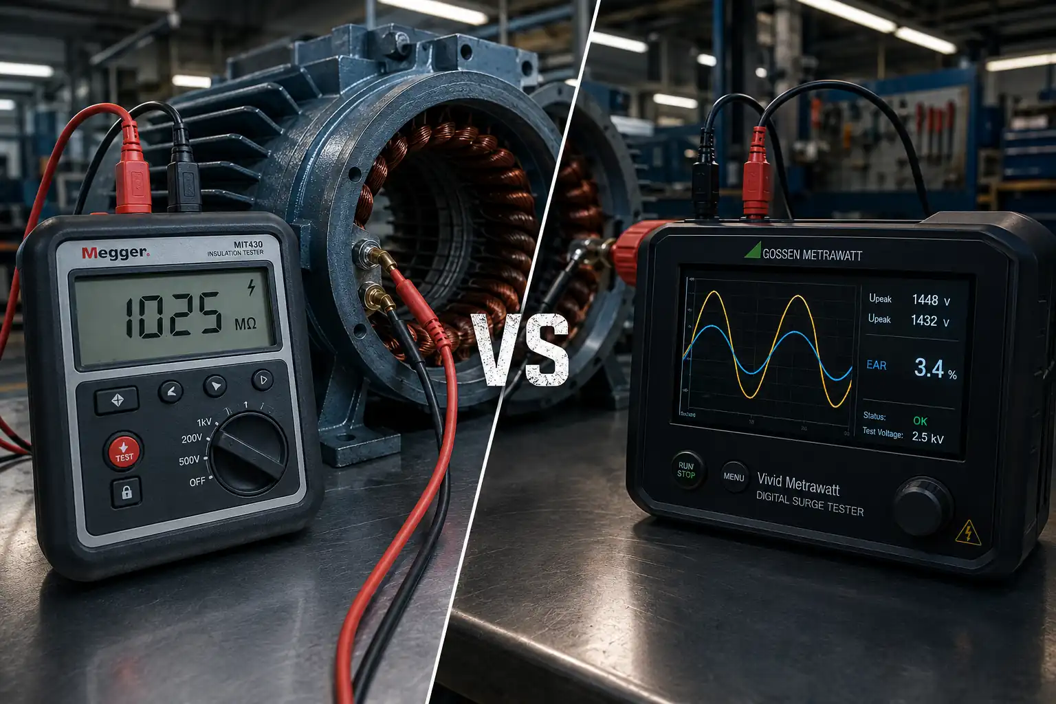
The core insight: A turn-to-turn fault — the most common early-stage winding failure — produces zero change in a Megger reading. A Megger test will show a clean, high-resistance result on a winding with an active turn-to-turn short. Only a surge test will reveal it.
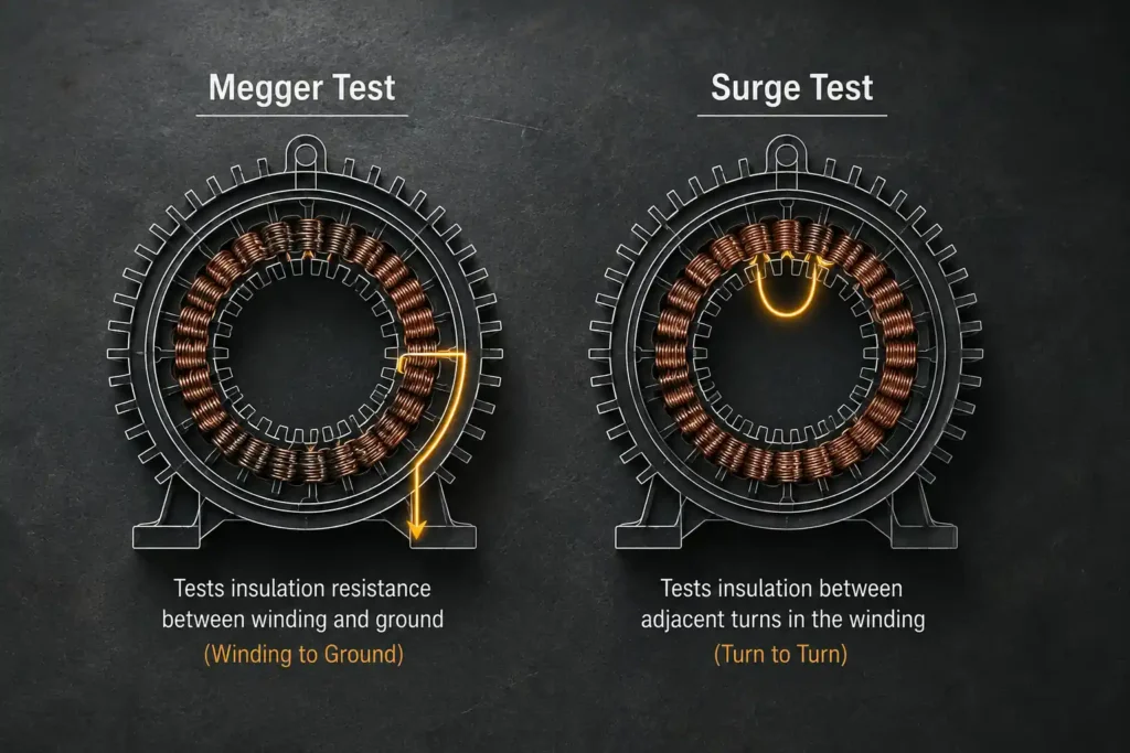
The Megger test is highly effective at evaluating the ground wall insulation — the main insulation barrier that protects the winding conductors from the motor’s earthed frame. Specifically, it identifies:
The Megger test’s critical limitation is structural: because it only measures the resistance between the winding and ground, any fault that exists entirely within the winding — with no path to ground — produces no measurable change in the result. This includes:
Practical example: A three-phase stator with two turns shorted together in one phase will show a Megger resistance of 100 MΩ or more — a pass result. The same winding will show a clearly deviated waveform on a surge tester, immediately identifying the fault location and phase.
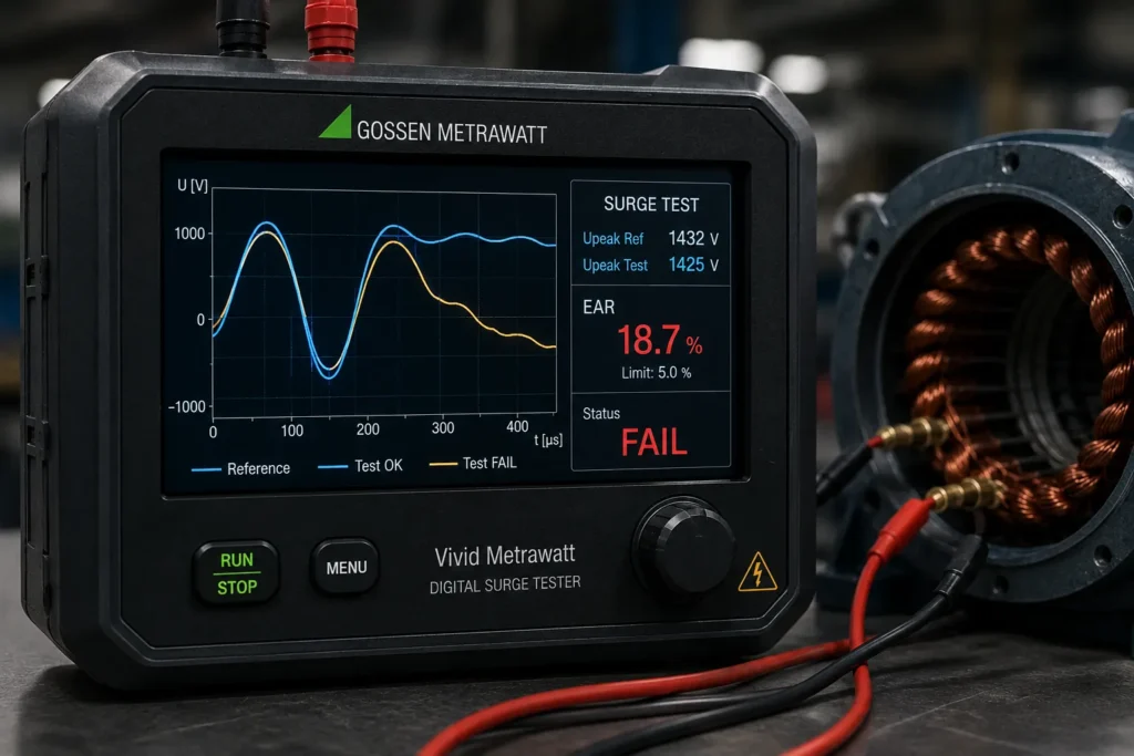
The surge test (impulse test) targets turn-to-turn and coil-to-coil insulation faults — the faults that the Megger cannot see. By applying a fast-rising high-voltage impulse and comparing the resulting waveforms across phases or against a reference, the digital surge tester identifies:
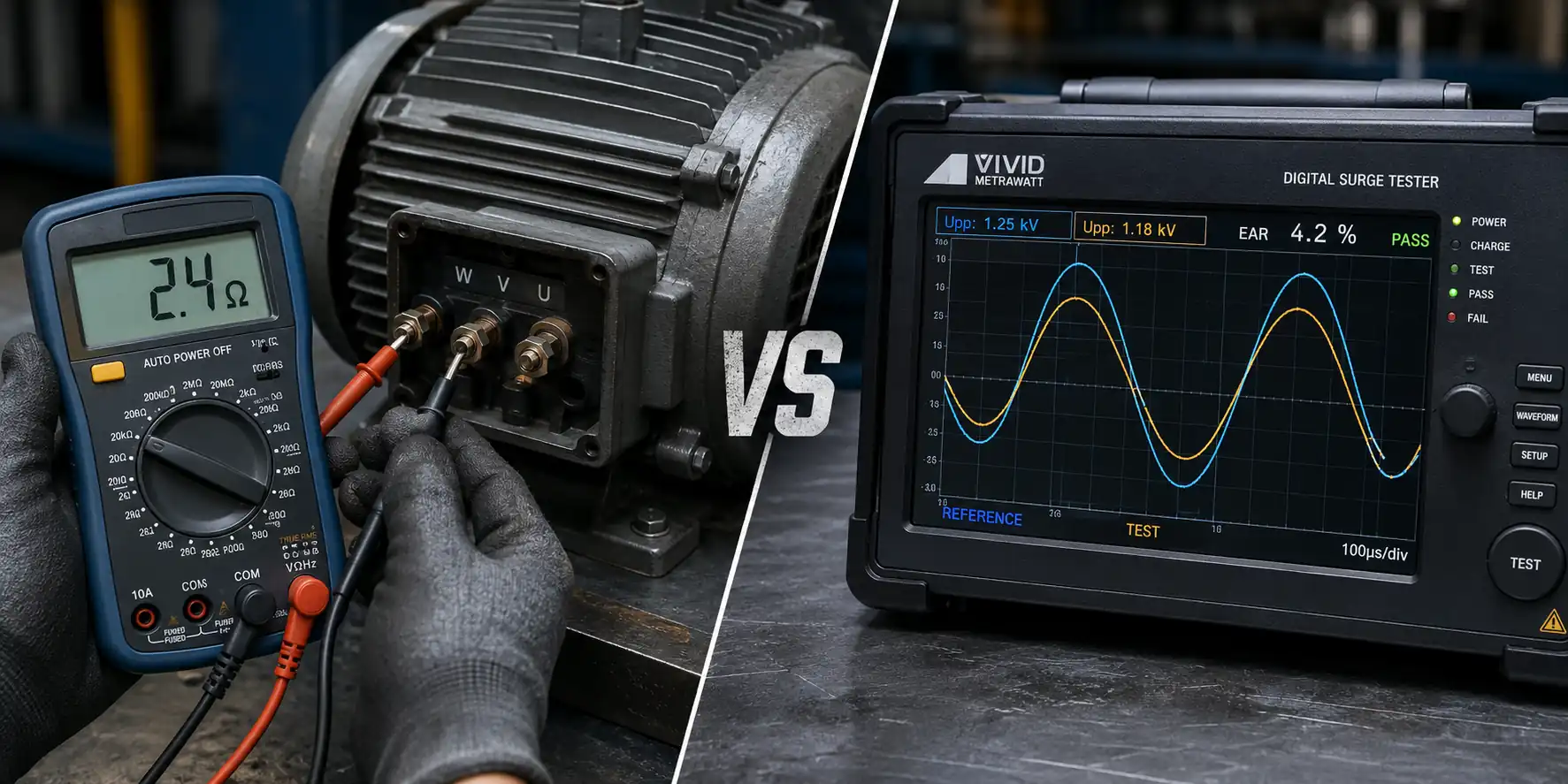
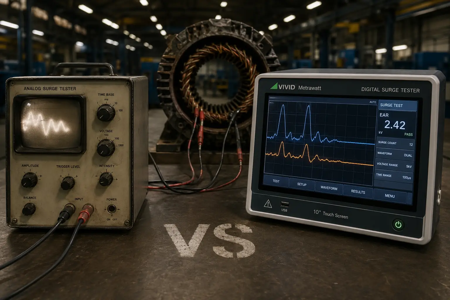
The result is displayed as a waveform comparison on the instrument screen. When both phases are healthy and matched, the waveforms overlap with precision. A deviation — a frequency shift, waveform collapse, or amplitude difference — is quantified by the Error Area Ratio (EAR) and indicates a fault or imbalance. See our detailed guide on waveform analysis in surge testing for a full explanation of how to read and interpret surge test results.
The surge test is focused entirely on the winding’s internal insulation between turns and coils. It is less sensitive to:
| Parameter | Megger Test (Insulation Resistance) | Surge Test (Impulse Winding Test) |
|---|---|---|
| What it tests | Ground wall insulation — winding to frame | Turn-to-turn and coil-to-coil insulation — within the winding |
| Voltage applied | Steady DC: 500V, 1000V, or 2500V | Fast impulse: 1KV to 50KV peak (matched to winding class) |
| Measurement output | Resistance value in megohms (MΩ) | Waveform comparison + Error Area Ratio (EAR %) |
| Detects turn-to-turn shorts? | ❌ No | ✅ Yes — primary purpose |
| Detects ground insulation faults? | ✅ Yes — primary purpose | ⚠️ Indirectly — not its primary function |
| Detects moisture ingress? | ✅ Yes — low resistance reading | ⚠️ Only if moisture has caused a turn-to-turn fault |
| Test duration | 1 to 10 minutes per test (PI test: 10 min) | Seconds per phase — fast production-compatible |
| Applicable standard | IEEE 43, IEC 60034-1 | IEEE 522, IEC 60034-15 |
| Typical use stage | Incoming inspection, periodic maintenance, before energisation | Post-rewind QC, OEM production end-of-line, acceptance testing |
| Can it replace the other? | ❌ No | ❌ No |
The Megger test belongs in your protocol at these specific points in the motor’s life cycle:
Note on Megger vs Hi-Pot: The Megger test and the DC Hi-Pot test are both ground insulation tests, but they serve different purposes. The Megger measures resistance (is the insulation healthy?); the DC Hi-Pot test applies a stress voltage (can the insulation withstand it?). See our detailed guide on AC Hi-Pot vs DC Hi-Pot testing for the full comparison.
The digital surge tester is the correct instrument at these specific points:
For further detail on the full range of applications across industries, see our guide on applications of the digital surge tester.
This is the central message of this guide, and it bears stating plainly: a complete winding qualification requires both the Megger test and the surge test, because they test different failure modes that cannot be revealed by the other.
A motor that passes only the Megger test has confirmed ground insulation integrity — but may have active turn-to-turn faults that will cause it to run hot, lose efficiency, and fail within weeks of installation.
A motor that passes only the surge test has confirmed turn-to-turn insulation integrity — but may have compromised ground insulation from moisture or contamination that will cause a phase-to-ground breakdown when energised.
The complete, professionally sound winding test sequence — whether for a rewound stator, a new OEM motor, or a motor returned from the field — runs in this order:
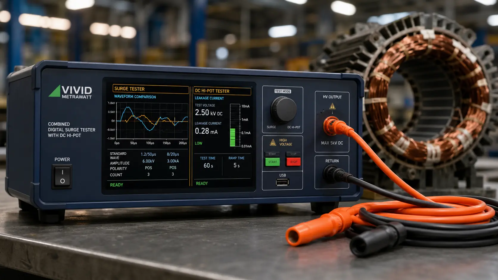
Vivid Metrawatt’s surge tester range includes models that combine surge testing and DC Hi-Pot in a single instrument — removing the need for two separate setups and two sets of connections for steps 3 and 4. For more on the relationship between these tests, see our blog on what Hi-Pot means in a digital surge tester.
Vivid Metrawatt manufactures digital surge testers from 1KV to 50KV — CE certified, IEEE and IEC compliant — with 89% of Indian Railway’s surge testers supplied by Vivid Metrawatt. The range covers every winding voltage class and workflow, from small workshop bench use to high-volume OEM production lines and high-voltage generator acceptance testing.
Key models relevant to winding qualification programmes:
For the full product range with specifications, visit the Vivid Metrawatt Digital Surge Tester page.
No. A surge tester tests turn-to-turn insulation integrity within the winding. It does not measure ground wall insulation resistance. A motor with excellent surge test results may still have compromised ground insulation from moisture or contamination that will cause a phase-to-ground breakdown when energised. Both tests are required for complete winding qualification.
No. A Megger test measures the resistance between winding conductors and ground. A turn-to-turn short — where two adjacent wire turns are in contact with each other — has no path to ground and produces no change in the Megger reading. A winding with an active turn-to-turn fault can return a Megger result well above the minimum acceptable threshold. Only a surge test will detect it.
The standard sequence is: visual inspection → Megger test → surge test → DC Hi-Pot test (if required). Always perform the Megger test before the surge test to confirm that ground insulation is in acceptable condition before applying high-impulse surge voltages. Performing a surge test on a winding with severely degraded ground insulation may cause a ground fault during the test.
Per IEEE 43, the minimum acceptable insulation resistance for a motor winding at operating temperature is 1 MΩ per 1 kV of rated operating voltage, plus 1 MΩ. For a 415V motor this is approximately 1 MΩ minimum; for a 6.6kV motor it is approximately 7 MΩ minimum. However, trending — tracking the resistance value over multiple tests — is more diagnostically valuable than a single pass/fail threshold.
Yes. Several Vivid Metrawatt surge tester models integrate DC Hi-Pot testing alongside the surge test function in a single instrument — including the 5KV / 6KV with DC Hi-Pot, the 10KV / 12KV / 15KV with Hi-Pot, and the 25KV / 30KV / 40KV with DC Hi-Pot. These allow surge and Hi-Pot testing to be completed in a single connection setup, reducing test time and the risk of connection errors.
Error Area Ratio (EAR) is a quantitative, objective measurement of the difference between two compared waveforms, expressed as a percentage. The higher the EAR, the greater the waveform divergence — and the more significant the insulation fault or winding imbalance. EAR enables a consistent, operator-independent pass/fail decision rather than relying on visual waveform comparison. For a full explanation, see our guide on what is Error Area Ratio.
When correctly applied at the voltage level specified by the applicable standard (IEEE 522 or IEC 60034-15), the surge test is non-destructive to healthy windings. The impulse is a very short-duration pulse — milliseconds — that stresses the turn-to-turn insulation sufficiently to reveal faults without degrading healthy insulation. Applying the test at voltage levels significantly above the standard recommendation increases the risk of stress damage.
Complete Your Winding Testing Programme with Vivid Metrawatt
The Megger test tells you your ground insulation is intact. The surge test tells you your winding is. Run both — and run them on equipment that has been trusted by Indian Railways and industrial facilities across more than 30 export countries for nearly 30 years.
→ Explore the Full Digital Surge Tester Range