
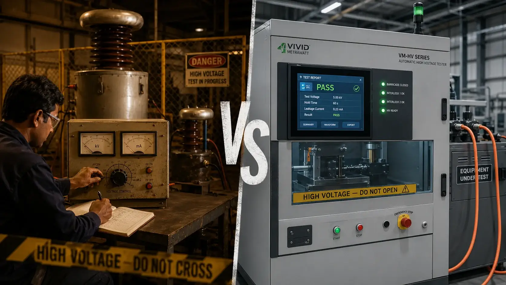
Manual high-voltage testing has been used in electrical quality assurance for decades — and it works, under the right conditions: an experienced, trained operator; a controlled environment; meticulous manual record-keeping; and a programme where speed and audit-trail quality are secondary to simply obtaining a pass/fail. In modern production environments, laboratories, and quality management systems, none of those conditions reliably hold. The case for an automatic high voltage tester over manual HV testing is not about technology preference — it is about removing operator-dependent error from a safety-critical measurement, producing results that are legally and contractually defensible, and integrating HV testing into a production workflow that cannot afford the throughput penalty of manual operation. This guide presents every meaningful difference between the two approaches, based only on what Vivid Metrawatt’s VM-HV Series is confirmed to deliver.
Table of Contents
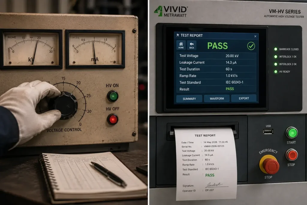
In manual HV testing, a high-voltage transformer or variable HV source is connected to the equipment under test. The operator manually adjusts a voltage control to raise the output voltage to the required test level, reads the voltmeter and ammeter from the panel, makes a pass/fail judgement, and records the result in a paper logbook. At the end of the test, the voltage is manually reduced and the test leads are disconnected.
Every step requires operator action and involves a human judgement or measurement. The quality of the result depends directly on the skill, attentiveness, and discipline of the individual performing the test.
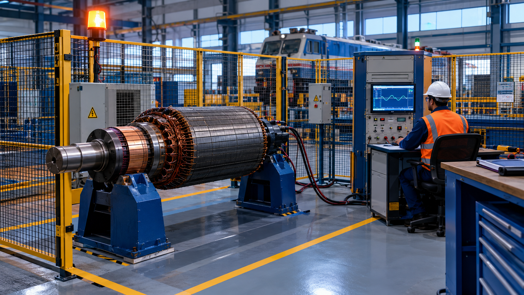
In automatic HV testing — as delivered by the Vivid Metrawatt VM-HV Series — the operator connects the test leads, selects a pre-programmed test configuration on the HMI, and initiates the test. From that point, the instrument manages the entire sequence automatically: verifying safety interlock status, ramping voltage at a controlled rate, holding at the test voltage for the specified duration, continuously monitoring leakage current, comparing measured current against the acceptance threshold, determining pass or fail, ramping down, discharging safely, and generating a complete test record and report.
No manual voltage adjustment. No panel-meter reading. No manual recording. The result is the same every time, regardless of which operator initiates the test.
The defining difference: Manual HV testing converts the operator into a measurement instrument. Automatic HV testing uses the operator only to set up and initiate — the instrument handles measurement, evaluation, and recording with no human intervention in the critical steps.
Manual HV testing is not wrong in principle — but it has structural limitations that are inherent to the approach, not addressable by better training or more careful operators:
The operator sets the test voltage by adjusting a control and reading a voltmeter. Accuracy depends on voltmeter calibration, control resolution, and operator care. Step changes, overshoot, and under-voltage are all possible — and none are automatically detected or recorded. The VM-HV Series ramps voltage to the programmed test level at a controlled rate defined in software, with real-time confirmation that the actual output matches the programmed level throughout the test.
The operator reads leakage current from an analogue ammeter and decides whether it is within the acceptable limit. An analogue needle between two scale divisions requires interpretation. Under time pressure or at the end of a shift, that interpretation is less reliable. The automatic VM-HV Series measures leakage current continuously and with precision, applies the acceptance threshold mathematically, and delivers an objective result with no judgement involved.
Manual instruments have no programmed acceptance threshold. There is no automatic alarm or trip on over-current, and no instrument-determined pass/fail. The operator decides — and different operators on the same shift may apply the threshold differently. The VM-HV Series applies a consistent, pre-programmed threshold on every test.
Manual testing produces no digital record. The result exists only as a handwritten logbook entry, which may be incomplete, transcribed incorrectly, or lost. There is no retrievable record of the exact leakage current, the actual applied voltage, the test duration, or the time and date. The VM-HV Series records all of these automatically for every test.
Creating a formal test report from manual HV testing requires someone to transfer handwritten data into a report template — introducing transcription errors and consuming time incompatible with high-throughput production environments. The VM-HV Series generates the report automatically at the end of each test.
In manual testing, voltage is raised by the operator turning a control — which may produce an uncontrolled step change if turned too quickly. An abrupt voltage step can cause a transient stress different from the intended withstand test. The VM-HV Series ramps at a controlled, software-defined rate.
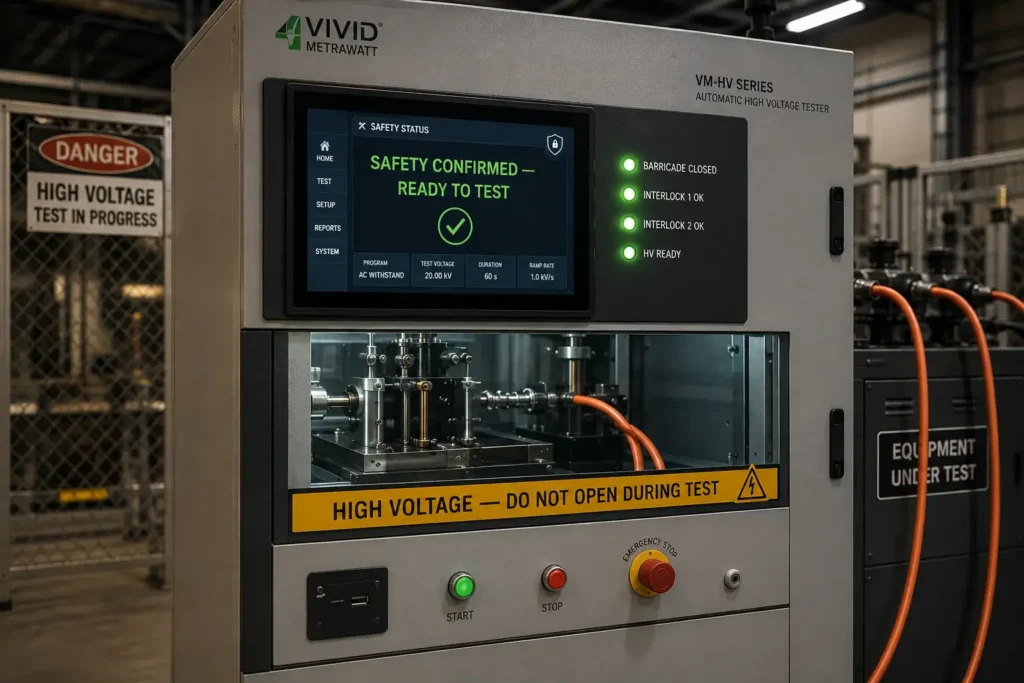
Manual HV testing has no automated safety interlocks. If the test area is accessed during a live test, the instrument does not know and does not respond. Safety in manual HV testing depends on physical barriers, warning signs, written procedures, and operator discipline — all of which can fail. The VM-HV Series integrates a safety barricading system with hardware interlocks that physically prevent HV output if the test area is entered.
Based on confirmed product specifications across all four VM-HV models — 15kV, 20kV, 30kV, and 40kV — here is what the Vivid Metrawatt automatic HV tester delivers that no manual setup can replicate:
| Parameter | Manual HV Testing | VM-HV Series Automatic HV Testing |
|---|---|---|
| Voltage setting | Manual — operator adjusts variac; accuracy depends on calibration and operator care | Software-programmed — precise, repeatable, controlled ramp; no operator adjustment during test |
| Leakage current measurement | Analogue ammeter — operator reads and interprets needle | Continuous real-time digital measurement — no operator reading required |
| Pass/fail determination | Operator judgement — subjective, variable between individuals | Automatic — instrument applies pre-programmed threshold; consistent on every test |
| Voltage ramp control | Manual — speed and smoothness depend on operator technique | Software-controlled — consistent ramp rate defined in test programme |
| Data logging | None — handwritten logbook only | Automatic — every test parameter and result recorded digitally |
| Report generation | Manual — handwritten or typed; error-prone and time-consuming | Automatic — instant professional report at test completion |
| Test repeatability | Variable — operator-to-operator and session-to-session variation | Consistent — identical parameters on every run; no operator variability |
| Safety interlocks | None built-in — relies on physical barriers and operator discipline | Hardware interlocks integrated — auto-shutdown on interlock breach during test |
| Safety barricading | External — separate barrier; not linked to instrument HV output | Integrated — barricading system built into instrument and electrically interlocked to HV output |
| Production line suitability | Limited — operator-paced; manual documentation creates bottleneck | High — automated sequence; fast cycle; automatic documentation; no bottleneck |
| Audit trail quality | Weak — paper records; no way to verify accuracy of recorded values | Strong — digitally logged, timestamped, instrument-verified records for every test |
| Standards compliance documentation | Difficult — no instrument-generated evidence of precise test parameters | Straightforward — automatic report provides complete, verifiable test evidence |
High voltage testing is one of the highest-risk activities in any electrical testing environment. The voltages involved in the VM-HV Series — 15kV to 40kV — are lethal at accessible current levels. A single safety failure has immediate and irreversible consequences.
In manual HV testing, safety rests on a chain of human and procedural controls: a physical barrier, a warning sign, a written procedure, and operator memory and discipline. Every link in this chain depends on human performance — which is not constant across fatigue, distraction, time pressure, and experience levels.
In the VM-HV Series, safety is hardware-enforced:
This is the single most operationally important distinction between automatic and manual HV testing — and it applies regardless of production pressure, operator experience, or shift conditions.
Important: The VM-HV Series’ integrated safety system does not replace the requirement for formal HV safe working procedures, operator HV safety training, and lockout/tagout programmes. Hardware interlocks supplement — they do not substitute for — a properly managed safety system. Both are required.
In regulated manufacturing and QMS environments — ISO 9001, IATF 16949 (automotive), AS9100 (aerospace), or sector-specific standards — every quality test result must be traceable, verifiable, and retrievable. The test record must show not just pass/fail, but the exact test parameters: actual applied voltage, measured leakage current, test duration, date and time, and equipment identification.
Manual HV testing cannot reliably provide this. A handwritten logbook entry records what the operator chose to write — not necessarily what the instrument measured. There is no way to verify that the recorded voltage was the actual applied voltage, or that the recorded current was the measured current at that moment.
The VM-HV Series provides instrument-generated evidence for every test:
This documentation capability is essential for motor manufacturers supplying automotive OEMs, transformer manufacturers supplying utilities, and cable manufacturers certifying infrastructure products. For how the HV withstand test fits within a broader motor insulation test programme — alongside Megger and surge testing — see our guide on the difference between Megger and surge testing for windings.
In a production environment, the HV withstand test is a mandatory quality gate — every unit must pass before progressing. Manual HV testing creates three distinct throughput constraints:
The VM-HV Series eliminates all three. Once the test configuration is programmed, each subsequent test requires only connecting leads, selecting the programme, and initiating. The instrument manages the rest — including automatic documentation — while the operator prepares the next unit. Cycle time is faster, consistency is higher, and documentation is complete with no administrative burden added to the operator.
For context on how the HV withstand test sits within a complete motor winding test sequence, see our guide on how to test motor windings.
An honest comparison acknowledges that manual HV testing retains legitimate use cases — specifically where the structural limitations are mitigated by the nature of the work:
In all other contexts — particularly any production, quality assurance, or standards-compliance testing environment — the automatic HV tester is the technically and operationally superior choice.
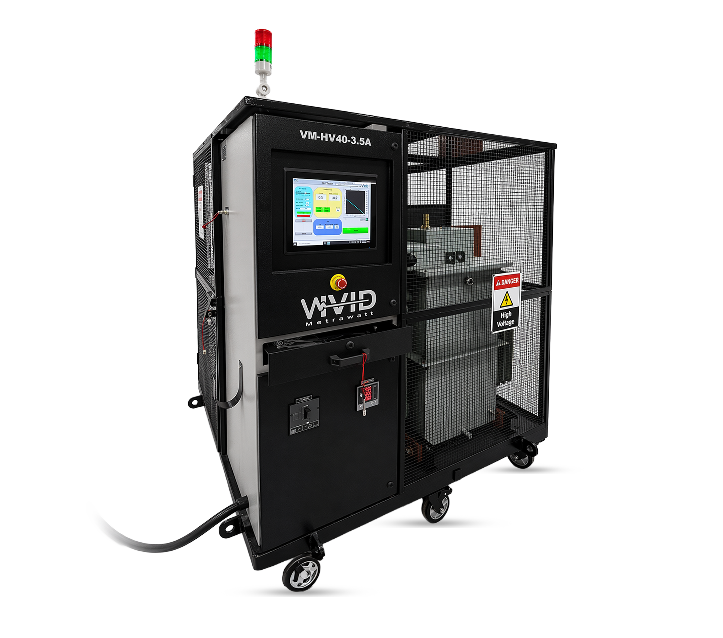
The Vivid Metrawatt VM-HV Series is available in four voltage ratings, each with sub-models (-1A to -5A) for different current output requirements. All models carry the same complete feature set:
| Model | Max Voltage | Sub-Models | Primary Use |
|---|---|---|---|
| VM-HV15 | 15kV | VM-HV15-1A to VM-HV15-5A | Motors, stators, coils, transformers, cables — up to ~6.6kV operating class |
| VM-HV20 | 20kV | VM-HV20-1A to VM-HV20-5A | Medium-voltage motors, transformer coils, cable assemblies |
| VM-HV30 | 30kV | VM-HV30-1A to VM-HV30-5A | Traction motors, HV generator coils, distribution transformers, production QA labs |
| VM-HV40 | 40kV | VM-HV40-1A to VM-HV40-5A | Large transformers, HV motors, specialist cables, aerospace, defence, power utilities |
IEEE and IEC compliant. CE certified. 30+ years manufacturing. Supplied to 30+ countries. Custom solutions available. For the full product listing, visit the Vivid Metrawatt Automatic High Voltage Tester page.
To understand how the VM-HV Series fits alongside Vivid Metrawatt’s digital surge tester range in a complete motor and winding qualification programme, see our comparison of surge tester vs HiPot tester. For applications requiring both surge and DC HiPot in a single instrument, see the 10kV/12kV/15kV Digital Surge Tester with Hi-Pot.
In manual HV testing, the operator sets the voltage, reads leakage current from an analogue meter, makes the pass/fail decision, and records the result by hand. In automatic HV testing — delivered by the Vivid Metrawatt VM-HV Series — the instrument controls the entire sequence: voltage ramp, measurement, pass/fail determination, data logging, and report generation. The operator initiates the test; the instrument delivers the result.
Yes — structurally safer. The VM-HV Series integrates a hardware safety barricading system with interlocks that physically prevent HV energisation unless all safety conditions are confirmed. Any interlock opening during a test immediately shuts down HV output automatically. Manual setups rely on physical barriers and operator discipline — both of which can fail. This does not eliminate the need for formal safe working procedures and operator training, but it adds a hardware-enforced safety layer that manual setups cannot provide.
Yes. Test parameters — voltage level, ramp rate, hold duration, and leakage current acceptance threshold — are set in software and saved as named test programmes. The appropriate programme is selected and recalled at the start of each test session without re-entering parameters, eliminating setting errors on repeat tests of the same equipment type.
Yes. The VM-HV Series generates automatic test reports at test completion — including the pass/fail result, measured leakage current, actual applied voltage, test duration, date/time stamp, and equipment identification. These reports serve as the documented test evidence required by customer QMS, acceptance test procedures, and standards compliance records.
The instrument automatically detects the exceedance, immediately trips the HV output, assigns a fail result, and logs all test data. No operator action is required to respond. The fail result and data are available in the automatically generated test report.
They perform different, complementary tests. The automatic HV tester performs the dielectric withstand test — verifying ground wall insulation withstand capability. The digital surge tester performs the impulse winding test — verifying turn-to-turn insulation integrity. Both are required in a complete motor or transformer qualification programme. Vivid Metrawatt supplies both: VM-HV Series for HV withstand and the digital surge tester range (1kV to 50kV) for impulse winding testing.
Yes. Vivid Metrawatt offers custom solutions from specification to finished instrument. If your application requires a configuration outside the standard VM-HV Series, contact Vivid Metrawatt’s engineering team to discuss your requirements.
Replace Manual HV Testing with a System You Can Document and Defend
The VM-HV Series gives you every test result automatically logged, every report generated instantly, and every operator protected by hardware interlocks — not just procedural warnings. CE certified, IEEE and IEC compliant. Designed and manufactured by Vivid Metrawatt, trusted by Indian Railways and industrial facilities across 30+ countries for nearly 30 years.
→ View Automatic High Voltage Tester – 15kV
→ View Automatic High Voltage Tester – 20kV
→ View Automatic High Voltage Tester – 30kV

![Surge Testing for Wind Turbine Generators: Complete Guide [2026]](https://vividmetrawattglobal.com/wp-content/uploads/2026/09/a_wide_cinematic_industrial_outdoor_scene_at_an_o.webp)