![Which Surge Tester KV Rating Do You Need? 1KV vs 3KV vs 6KV vs 15KV [2026 Buyer’s Guide]](https://vividmetrawattglobal.com/wp-content/uploads/2026/09/wide_well_lit_industrial_workshop_scene_a_clean.webp)

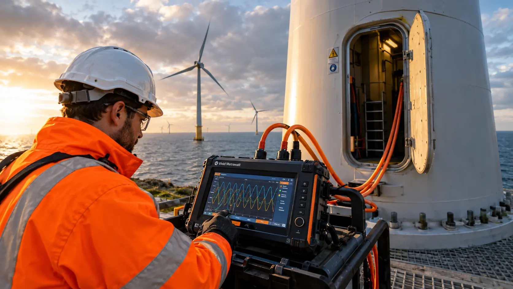
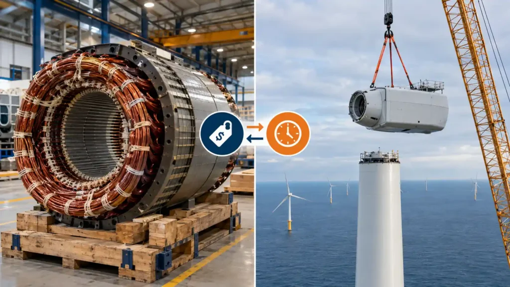
A wind turbine generator sits 80 to 120 metres above ground in a nacelle accessible only by a confined internal ladder or a service crane. When its stator winding fails in service — from a turn-to-turn insulation fault that was present but undetected before commissioning, or from insulation that degraded silently over years of thermal cycling — the consequences are not a routine maintenance call. They are a crane mobilisation, a turbine offline for weeks, and a repair or replacement cost that runs to hundreds of thousands of pounds, euros, or dollars. Surge testing for wind turbine generator windings is the quality gate that catches these faults before they become field failures — at the manufacturing stage, before rewind, and after maintenance. This guide covers exactly what the test involves, which winding voltage classes require which KV rating, the complete test protocol, and the Vivid Metrawatt instruments confirmed for wind energy generator applications.
Table of Contents
Wind turbine generators operate under conditions that are punishing for winding insulation. The combination of factors is unique among power generation equipment:
In this operational context, the financial and operational cost of an undetected turn-to-turn insulation fault — one that passes a standard resistance check and a Megger test but fails in service six months after commissioning — is vastly greater than the cost of a comprehensive surge test at the manufacturing, rewind, or commissioning stage.
The turn-to-turn insulation fault is the failure mode that only surge testing reliably detects. It is also the most common early-stage winding failure mode in both newly wound and service-aged generator stators. The surge test is the quality gate that stands between a detectable defect and a multi-week turbine outage.
Key principle: Every wind turbine generator stator winding — whether newly manufactured, rewound after failure, or returned to service after maintenance — should pass a surge test before it is installed. Once it is 80 metres up inside a nacelle, the cost of discovering a winding fault has increased by an order of magnitude.
Wind turbines generate electricity through a generator whose stator winding produces the AC output. The voltage class of that winding determines the surge tester KV rating required to perform a meaningful and standards-compliant test. Understanding this relationship is the foundation of correct equipment selection.
Common in modern large wind turbines (2MW–15MW class), direct drive PMSGs eliminate the gearbox and connect the rotor directly to the generator shaft. Their stator windings typically operate at medium voltages — commonly in the 690V to 3.3KV range at the generator terminals, stepped up by a transformer for grid connection. At 690V, the required surge test voltage (2 × 690V + 1000V = 2,380V) is within the 3KV range. At 3.3KV, the required surge test voltage (2 × 3300V + 1000V = 7,600V) places it firmly in the 10KV to 15KV class.
DFIGs are widely used in variable-speed wind turbines, particularly in the 1.5MW–3.5MW class. The stator winding connects directly to the grid — typically at 690V to 3.3KV at the generator terminals. Both stator and rotor windings require surge testing, though at different voltage levels. The stator winding test typically requires the 10KV to 15KV class; the rotor winding (connected to the converter) at lower voltage may fall in the 3KV to 6KV range depending on the design.
Used in smaller and some legacy turbines, operating typically at 400V to 690V. Surge test voltage requirement falls within the 3KV range.
Offshore turbines of the latest generation — 5MW, 8MW, 12MW, and 15MW class — typically employ generators with stator voltages of 6.6KV to 11KV at the generator terminals. At 6.6KV, the required surge test voltage is approximately 14,200V — confirmed within the 15KV model’s range. At 11KV, the required test voltage is approximately 23,000V — requiring the 25KV model.
Key takeaway: There is no single KV rating that covers all wind turbine generator types. The correct surge tester KV rating depends on the generator’s operating voltage class. Always identify the generator’s rated stator voltage before specifying the test instrument — then apply the standard formula: Surge Test Voltage = 2 × Vrated + 1000V, and select the surge tester whose KV rating comfortably exceeds this value.
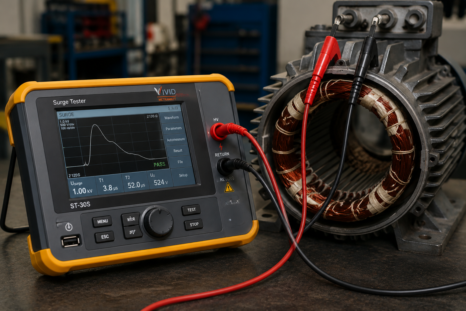
The digital surge tester applies a controlled, fast-rising high-voltage impulse to the generator stator winding and compares the resulting oscillating waveform against a reference phase or stored master waveform. In a healthy, balanced stator, the waveforms from each phase are identical — they superimpose on the display. Any deviation indicates a fault within the winding.
In wind turbine generator stator windings specifically, surge testing reliably detects:
What surge testing does not detect — and what must be covered by complementary tests:
For a detailed explanation of how EAR quantifies the waveform deviation and produces an objective pass/fail result, see our guide on what is Error Area Ratio (EAR) in surge testing.
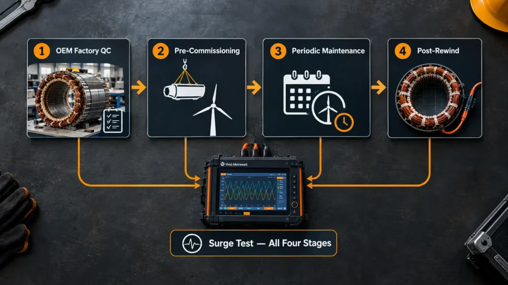
For wind turbine generator windings, there are four distinct points in the component’s life cycle where surge testing adds maximum value — each with a different purpose and a different cost-of-failure consequence if skipped.
Every generator stator winding should be surge tested before the generator is assembled into the nacelle. This is the highest-leverage test point — the cost of a surge test at the factory, before the stator leaves the production floor, is a fraction of the cost of a generator failure in the field. OEM surge testing is required by IEC 60034-15 (rotating electrical machines — impulse voltage withstand levels) and IEC 60034-1 (routine test requirements). The test catches winding faults introduced during the winding process: insulation nicks from conductor handling, insufficient turn insulation coverage, incorrect coil connections.
After the generator has been transported to site, lifted into the nacelle, and connected, but before the turbine is energised for the first time — a surge test confirms that transport and installation have not introduced new insulation damage. Transport vibration, thermal shock, and mechanical handling during installation can all degrade winding insulation that was intact when the stator left the factory. A pre-commissioning surge test provides the baseline waveform that will serve as the reference for all future comparison tests.
During scheduled maintenance intervals — typically annual or biennial for wind turbine generators — a surge test conducted with the generator offline compares current waveforms against the commissioning baseline. A change in the EAR value or a visible waveform shift between maintenance intervals indicates developing insulation degradation. This is the predictive maintenance application of surge testing: catching a deteriorating winding before it becomes a failed winding, and scheduling a planned rewind during a low-wind period rather than responding to an unplanned failure during peak generation season.
After any generator stator rewind — whether following a winding failure, scheduled life extension, or voltage class modification — the rewound stator must pass a surge test before it is reinstalled in the nacelle. The rewinding process introduces the highest risk of turn-to-turn insulation damage in a winding’s life: wire handling, slot insertion, end-winding forming, and varnish impregnation all carry the possibility of insulation damage between turns. No rewound stator should be reinstalled in a wind turbine without passing a surge test at the appropriate KV level for its voltage class.
The surge test voltage is calculated from the generator’s rated stator winding voltage, using the standard formula from IEEE 522:
The surge tester’s rated KV must comfortably exceed the calculated test voltage. The table below maps the most common wind turbine generator stator voltage classes to the appropriate Vivid Metrawatt model:
| Generator Stator Voltage | Turbine Class / Type | Calc. Test Voltage | Required KV Rating | Vivid Metrawatt Model |
|---|---|---|---|---|
| 400V – 690V AC | Small onshore turbines; asynchronous generators | 1,800V – 2,380V | 3KV | VM LCD-3AND (3KV) |
| 3.3KV AC | Medium onshore turbines; DFIG stator; direct drive PMSG | ~7,600V | 10KV | VM-10K or VM-10KHR (with Hi-Pot) |
| 6.6KV AC | Large onshore and offshore turbines; 3MW–8MW class | ~14,200V | 15KV | VM-15K or VM-15KHR (with Hi-Pot) |
| 11KV AC | Very large offshore turbines; 8MW–15MW class | ~23,000V | 25KV | VM-25K or VM-25KHR (with DC Hi-Pot) |
| 13.8KV AC | Largest offshore turbines; specialised generator designs | ~28,600V | 30KV – 40KV | VM-30K / VM-40K or VM-30KHR / VM-40KHR (with DC Hi-Pot) |
Always verify: Confirm the generator’s rated stator voltage from the OEM nameplate or technical datasheet before specifying the surge tester model. If the turbine’s generator has been rewound to a different voltage class, use the new rated voltage for KV selection — not the original nameplate voltage.
The following Vivid Metrawatt models are confirmed for testing AC motors, stators, armatures, transformers, alternators, and other wound electrical components — the application set that encompasses wind turbine generator stator windings across all voltage classes.
Product page: 10KV, 12KV & 15KV Digital Surge Tester
Confirmed for precise testing of coils and windings in AC rotating machines accommodating voltages up to 6.6KV. This covers the 3.3KV and 6.6KV stator voltage classes that represent the majority of current large onshore and offshore wind turbine generators. Three voltage sub-models (VM-10K, VM-12K, VM-15K) allow selection of the appropriate test voltage for the specific stator voltage class:
Confirmed features: Embedded industrial PC; 10-inch touch screen; LABVIEW software integration; infinite model storage; dual-feature waveform comparison (master waveform or simultaneous two-winding); colour-coded waveforms; automatic report generation in MS Word; comprehensive job work management.
Product page: 10KV, 12KV & 15KV Digital Surge Tester with Hi-Pot Test
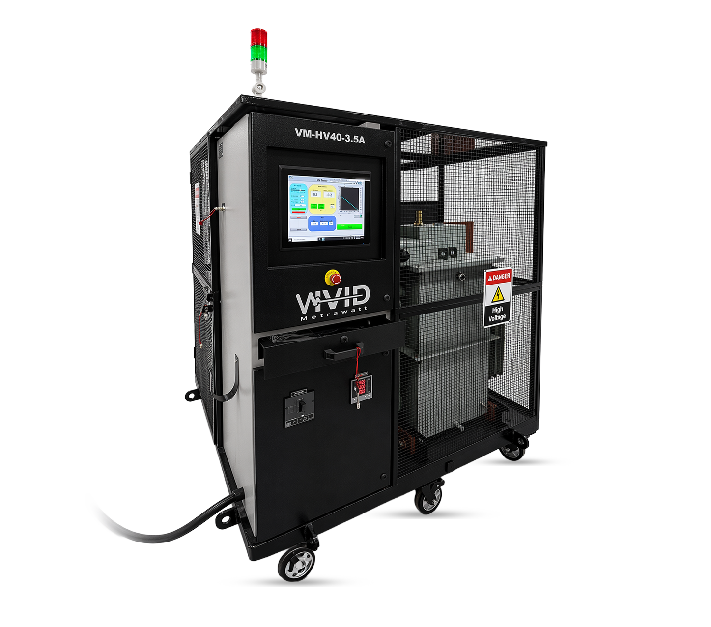
Adds integrated DC Hi-Pot testing to the full surge test capability of the VM-10K/12K/15K series. For wind turbine generator acceptance testing where both turn-to-turn insulation (surge) and ground wall insulation withstand (Hi-Pot) results are required in the test certificate, this combined instrument eliminates the need for two separate setups. This is the model to specify when your acceptance test protocol — or the turbine OEM’s requirements — mandates both test types on a single instrument.
Product page: 25KV, 30KV & 40KV Digital Surge Tester
Confirmed for precise testing of coils and windings in AC rotating machines accommodating voltages up to 13.8KV. This covers the 11KV to 13.8KV stator voltage classes found in the largest offshore wind turbine generators — 8MW to 15MW class turbines. The 80KV-rated test leads and footswitch for hands-free operation are confirmed features across this range.
Confirmed features: 10-inch touch screen; embedded industrial PC; LABVIEW; infinite model storage; colour-coded waveforms; automatic report generation; footswitch; test leads insulated up to 80KV.
Product page: 25KV, 30KV & 40KV Digital Surge Tester with DC Hi-Pot
Adds integrated DC Hi-Pot to the 25KV–40KV surge test capability. For the largest offshore wind turbine generator stators — where acceptance test protocols are the most stringent and where both surge and Hi-Pot results are required in the formal acceptance certificate — the combined instrument provides both tests in a single connected setup at 80KV insulated lead safety rating.
For the complete digital surge tester range including all KV classes, visit the Vivid Metrawatt Digital Surge Tester page.
The following protocol applies to surge testing of wind turbine generator stator windings — whether at OEM manufacturing, pre-commissioning, periodic maintenance, or post-rewind stage.
Before any electrical test is applied:
Before applying high-voltage surge testing, confirm the ground wall insulation condition with an insulation resistance (Megger) test. A severely degraded or wet ground wall insulation may fail during surge testing, causing additional damage and producing a misleading test result. The Megger test confirms the stator is in a condition suitable for HV testing. For the complete Megger test procedure, see our guide on the difference between Megger and surge test for windings.
Where the test protocol or acceptance certificate requires ground wall insulation withstand testing in addition to surge testing, apply the DC Hi-Pot test after the surge test has been passed. Never apply Hi-Pot before surge testing — a turn-to-turn fault, if present, may be aggravated by the sustained Hi-Pot voltage and propagate into a phase-to-ground breakdown, damaging the winding further. For more on the correct test sequence and the relationship between surge and Hi-Pot testing, see our guide on surge tester vs Hi-Pot tester.
All Vivid Metrawatt digital surge testers generate automatic test reports in MS Word via LABVIEW software. The report includes: test waveform data, EAR result, test voltage applied, date and time stamp, and component identification. For a wind turbine generator:
A complete wind turbine generator stator insulation qualification protocol requires three distinct test types, each addressing a different insulation structure. None can substitute for the others.
| Test | What It Tests | What It Detects | What It Cannot Detect | Sequence |
|---|---|---|---|---|
| Megger (IR Test) | Ground wall insulation resistance — winding to stator frame | Moisture ingress; contamination; gross insulation deterioration | Turn-to-turn faults; coil-to-coil weakness | First |
| Surge Test | Turn-to-turn insulation — inside the winding coil | Turn-to-turn shorts; coil-to-coil faults; winding imbalance; wrong connections | Ground wall insulation condition or withstand | Second |
| DC Hi-Pot | Ground wall insulation withstand — winding to frame | Ground wall insulation breakdown under sustained overvoltage | Turn-to-turn faults; winding balance | Third |
For a detailed explanation of the AC HiPot vs DC HiPot choice and when each type is appropriate for generator winding testing, see our guide on AC Hi-Pot vs DC Hi-Pot testing. For the complete waveform interpretation framework — including what a fault signature looks like versus a healthy winding — see our guide on waveform analysis in surge testing.
Wind turbine generator surge testing does not exist in isolation — it must meet documented standards and produce evidence that certifying bodies, turbine OEMs, and asset owners can verify. The relevant framework:
For a surge test on a wind turbine generator stator winding to be accepted by a certifying body or turbine OEM, the test report should include:
Vivid Metrawatt digital surge testers generate automatic test reports via LABVIEW software integration, providing all the data fields required for a complete, auditable test record. For best practice on maintaining calibration and ensuring that instrument records remain valid for certification purposes, see our guide on how to maintain and calibrate your digital surge tester.
Calibration note: For surge test results to be used as evidence in a formal acceptance test certificate, the instrument must hold a current calibration certificate traceable to national or international standards. Annual calibration is the standard recommended interval for most industrial applications. Wind energy certification bodies may require specific calibration documentation formats — confirm requirements with your certifying body before the test.
For a 6.6KV stator winding, the calculated surge test voltage is 2 × 6,600V + 1,000V = 14,200V. The correct instrument is the VM-15K (15KV Digital Surge Tester). If your acceptance test protocol also requires DC Hi-Pot testing, specify the VM-15KHR, which includes both surge and Hi-Pot in one instrument.
Only if its KV rating is appropriate for the generator’s stator voltage class. A 3KV model used for 415V industrial motors cannot adequately stress the insulation of a 3.3KV or 6.6KV wind turbine generator stator. Applying a 3KV instrument to a 6.6KV stator would produce a surge test voltage (3,000V) well below the required test voltage (14,200V), making the test meaningless. Always select the instrument based on the generator’s rated stator voltage — not based on what instruments are already available in the facility.
For most wind turbine generator configurations, surge testing is most practically and meaningfully performed with the stator winding accessible — typically with the rotor removed. Testing with the rotor installed is possible but requires careful attention to potential coupling effects between stator and rotor windings. In a maintenance context where the rotor cannot be removed, consult the turbine OEM’s maintenance manual for the correct procedure. At manufacturing stage and post-rewind, testing is always performed on the stator assembly before rotor installation.
The EAR (Error Area Ratio) acceptance threshold is not universally standardised at a single number — it varies by generator design, winding type, and the applicable standard or OEM specification. A common practice for new windings is an EAR threshold of 3–5% (a winding with all phases producing EAR below this threshold passes). For trending tests comparing current results against a commissioning baseline, any increase in EAR above 2–3% from the baseline is typically flagged for investigation, regardless of whether it crosses an absolute threshold. Always apply the threshold specified in the relevant standard (IEC 60034-15 or IEEE 522) or the turbine OEM’s test procedure.
There is no universally mandated interval — maintenance intervals vary by turbine OEM, asset owner, and maintenance contract specification. Common practice for planned maintenance programmes is surge testing at each major maintenance interval (typically annually or biennially), particularly for generators with a history of high thermal or moisture stress. Surge testing should always be performed after any event that could have damaged the winding insulation — including an overvoltage event, a lightning strike nearby, flooding of the nacelle, or any internal electrical fault.
Vivid Metrawatt’s digital surge tester range — including the 15KV and 25KV–40KV models with 80KV-insulated test leads — covers the voltage classes encountered in all current wind turbine generator types, including large offshore turbines. Wind energy is a confirmed served industry in Vivid Metrawatt’s product documentation. Custom solutions are also available — contact Vivid Metrawatt’s technical team to discuss requirements for specific turbine generator models or unusual test configurations.
Surge testing detects turn-to-turn and coil-to-coil insulation faults by applying a high-voltage impulse and comparing waveforms — it is a pass/fail test on the winding’s current insulation integrity. Partial discharge (PD) testing detects localised electrical discharges within the insulation system that indicate deterioration beginning to develop but not yet causing a fault — it is more sensitive for incipient failures in medium and high-voltage windings, particularly in the slot insulation of form-wound coils. The two tests are complementary: surge testing is the standard quality gate at manufacturing and post-rewind; PD testing is more appropriate for in-service condition monitoring of high-value medium-voltage generators operating above 3.3KV.
Specify the Right Surge Tester for Your Wind Turbine Generator
Whether you are qualifying generator stators at the manufacturing stage, performing acceptance testing before turbine commissioning, or building a predictive maintenance programme for an operating wind farm — Vivid Metrawatt’s digital surge tester range covers every wind turbine generator voltage class from 690V to 13.8KV+. CE certified. IEEE 522 and IEC 60034-15 compliant. Trusted across 30+ countries. Wind energy is a confirmed served industry.
→ 10KV / 12KV / 15KV Digital Surge Tester — for 3.3KV and 6.6KV generators
→ 10KV / 12KV / 15KV with Hi-Pot — combined surge + DC Hi-Pot in one instrument
→ 25KV / 30KV / 40KV Digital Surge Tester — for 11KV and 13.8KV generators
→ 25KV / 30KV / 40KV with DC Hi-Pot — combined surge + DC Hi-Pot for offshore generators