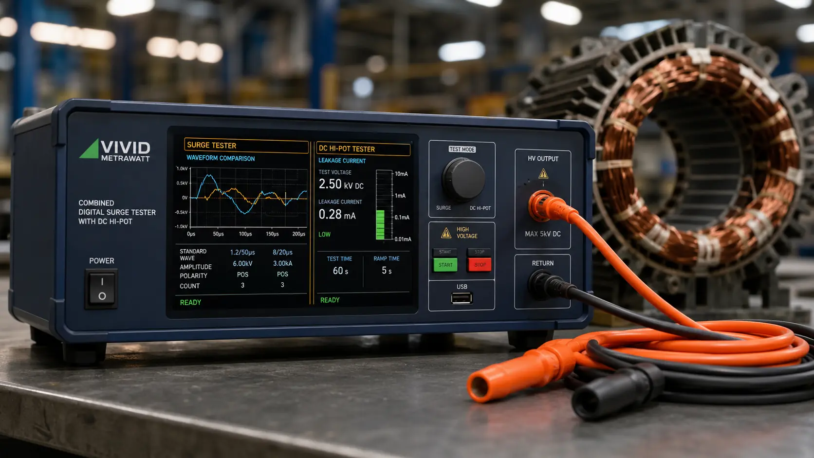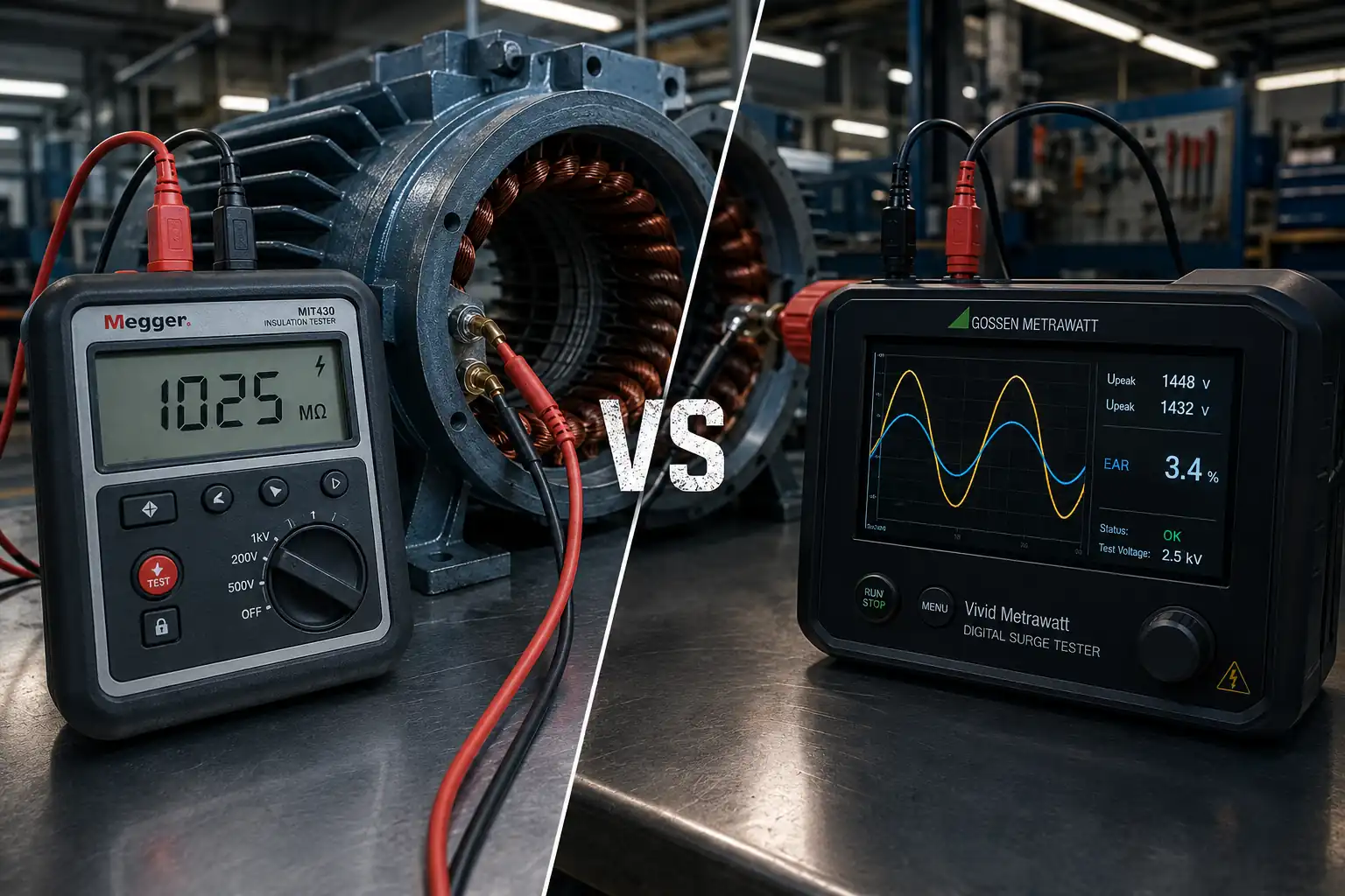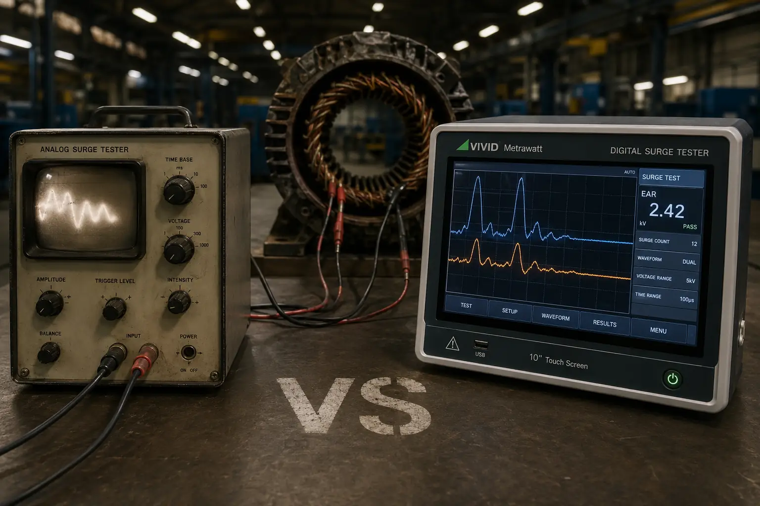

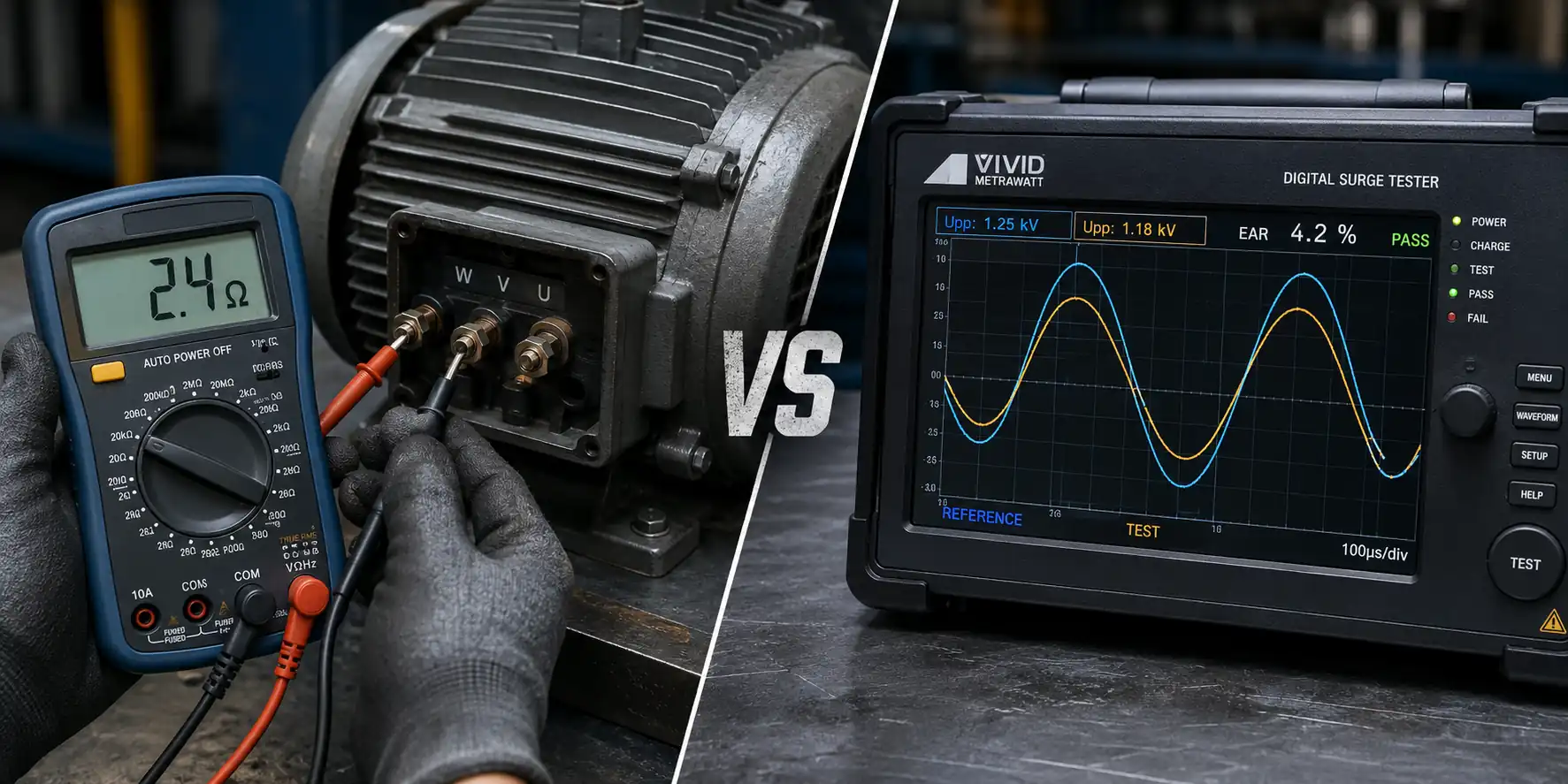
The resistance test says the winding is balanced — all three phases read within 2% of each other. The motor is rewound, returned to service, and fails with an internal short within a month. The resistance test did its job. The problem is that the fault it missed was never going to show up in a resistance reading. The surge test vs resistance test confusion costs maintenance teams real money because both tests are described as winding tests — but they interrogate entirely different insulation structures and catch entirely different failure modes. This guide explains exactly what each test reveals, what each one cannot see, and where they sit in your complete winding qualification sequence.
Table of Contents
These two tests are both described as winding tests and both appear in motor maintenance checklists — but they are measuring fundamentally different electrical properties, using different instruments, and detecting different failure categories.
The resistance test (DC resistance test or winding resistance test) uses a digital multimeter or a dedicated low-resistance ohmmeter to measure the DC resistance of each winding phase in ohms. The measurement is a simple, direct electrical property: how much opposition does the copper conductor present to direct current flow? The result reveals whether the conductor is intact, correctly wound, and balanced across phases.
The surge test (impulse winding test) uses a digital surge tester to apply a fast-rising, high-voltage impulse across the winding and analyse the resulting oscillating waveform. The measurement is a comparative, dynamic property: how does the winding’s turn-to-turn insulation behave under high-voltage stress? The result reveals whether the insulation between adjacent wire turns is intact and uniform across all phases.
The defining distinction: The resistance test checks the conductor — the copper wire path. The surge test checks the insulation between conductors — the varnish, enamel, and coating between wire turns. These are two separate materials, and each can fail independently of the other.
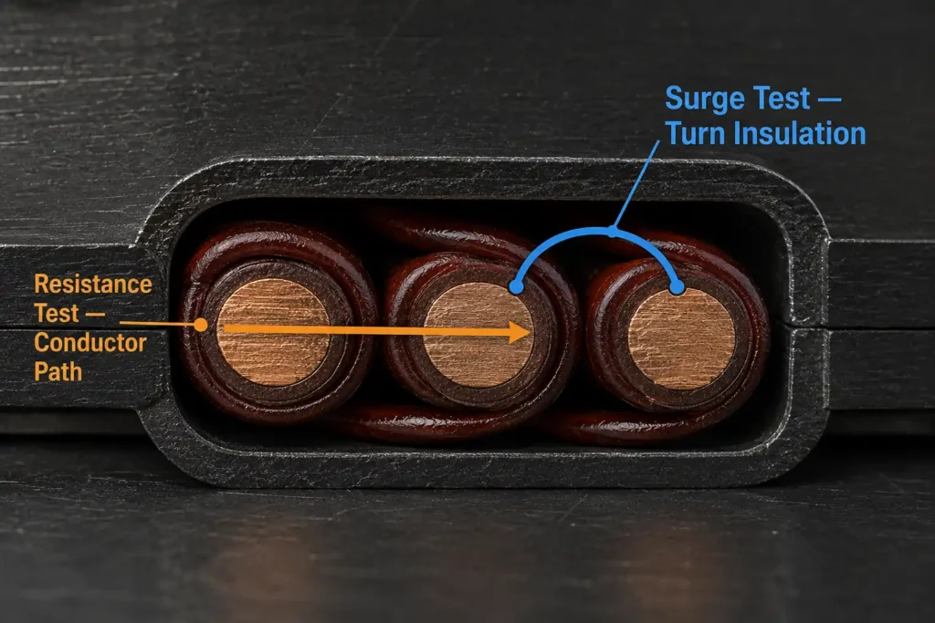
The DC winding resistance test is performed with a calibrated digital multimeter or a dedicated low-resistance ohmmeter. For a three-phase motor, the test measures resistance between each pair of terminals (U-V, V-W, W-U) and compares the three readings against each other. According to the procedure confirmed in Vivid Metrawatt’s motor winding testing guide at how to test motor windings, all readings should typically be within 5% of each other.
The resistance test reliably detects:
The resistance test’s limitation is a direct consequence of what it measures. It can only detect faults that change the resistance of the copper conductor path itself. Any fault that does not alter the conductor resistance is invisible to this test. This includes:
Practical reality: A three-phase stator with 200 turns per phase and 4 turns shorted in phase U will show phase resistances of approximately 2.40Ω (V and W phases) and 2.36Ω (U phase) — a 1.7% difference that is within the normal ±5% tolerance band. The resistance test passes. The winding has a fault that will cause localised overheating, reduced efficiency, and eventual catastrophic failure.
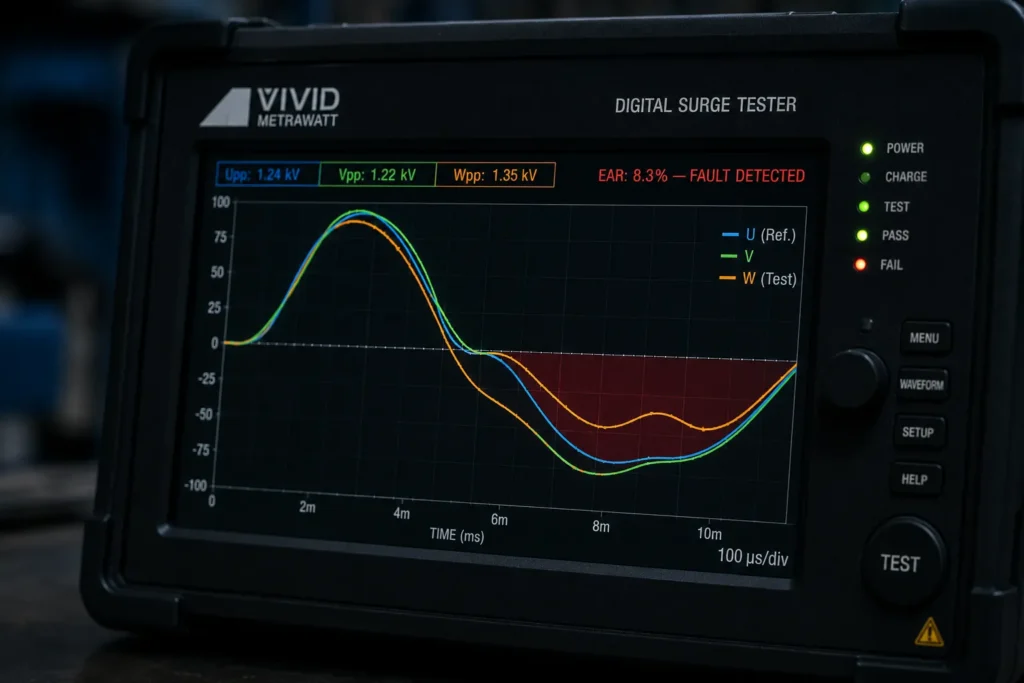
The digital surge tester applies a controlled, fast-rising high-voltage impulse to the winding under test and captures the resulting oscillating waveform. In a three-phase stator, the waveforms from each phase are compared against each other — or against a stored reference waveform from a known-good motor of the same type. When all phases are healthy and the turn-to-turn insulation is intact and uniform, the waveforms from each phase are identical. They superimpose on the display with precision.
When a turn-to-turn fault exists — even a small number of shorted turns — the resonant frequency and waveform shape of the affected phase changes. This deviation is captured digitally and quantified as the Error Area Ratio (EAR): the percentage difference in area between the reference and test waveforms. Even a small number of shorted turns produces a measurable, unmistakable EAR deviation.
The surge test reliably detects:
For a full explanation of waveform reading and EAR interpretation, see our guide on what is a surge tester.
The surge test is a turn-to-turn and coil-to-coil insulation test. It is less sensitive to:
| Parameter | Resistance Test (DC Winding Resistance) | Surge Test (Impulse Winding Test) |
|---|---|---|
| What it measures | DC resistance of copper conductor (ohms) | Turn-to-turn insulation integrity (waveform + EAR %) |
| Instrument used | Digital multimeter or low-resistance ohmmeter | Digital surge tester (1KV–50KV) |
| Voltage applied | Low DC (millivolts to a few volts — no HV risk) | High-voltage impulse (1KV–50KV peak) |
| Detects open circuits? | ✅ Yes — directly and immediately | ⚠️ Indirectly — waveform collapses on open phase |
| Detects turn-to-turn shorts? | ❌ No — resistance change too small to measure | ✅ Yes — primary purpose; detects even a few shorted turns |
| Detects insulation degradation? | ❌ No — conductor resistance is unaffected | ✅ Yes — degraded insulation causes waveform shift |
| Detects phase imbalance? | ✅ Yes — if large enough to show in resistance values | ✅ Yes — waveform divergence reveals even subtle imbalance |
| Test speed | Fast — seconds per phase measurement | Fast — seconds per phase; automatic on digital models |
| Operator skill required | Low — straightforward multimeter operation | Low to medium — digital models provide automatic EAR pass/fail |
| HV safety precautions required? | No — low voltage measurement | Yes — high-voltage impulse; HV safety procedures apply |
| Can it replace the other? | ❌ No | ❌ No |
This is the most commercially significant question in this comparison — and the one most relevant to motor repair shops, OEM production lines, and maintenance departments that rely on resistance testing as their primary or sole winding quality check after a rewind.
The rewinding process introduces the highest risk of turn-to-turn contact in any motor’s life cycle. Wire handling, placement in slots, endwinding forming, varnish impregnation, and baking all carry the possibility of insulation damage between adjacent turns — a nick, a pinhole, an area of insufficient varnish coverage. In the completed winding, this damage exists between two wire turns that are in contact through the compromised insulation, but still correctly connected at both ends.
From the resistance test’s perspective, this winding looks identical to a perfect winding. The short between two turns creates a small parallel path across those turns — slightly reducing the effective turn count and the measured resistance — but in a large winding, this change is far smaller than normal measurement variation caused by temperature, contact resistance at test probes, and conductor temperature coefficient.
From the surge test’s perspective, this winding tells a completely different story. The impulse stresses the insulation between those two shorted turns, and the waveform of the affected phase diverges from the reference immediately and measurably. The EAR value flags the fault. The motor is held before return to service, the fault is investigated, and the winding is corrected.
For this reason, every professional motor rewind quality programme includes surge testing as the mandatory final QC step — not as an optional add-on to the resistance test, but as the primary winding integrity verification tool. This is confirmed in published industry standards including IEEE 522 and IEC 60034-15, which define surge testing as the standard method for verifying turn insulation quality in rewound and new windings.
The resistance test has a well-defined and valuable role in the winding test sequence. Use it at these specific points:
Practical note: Temperature has a significant effect on copper conductor resistance — approximately +0.4% per °C. Always record the winding temperature at the time of resistance testing and correct to a standard temperature (typically 20°C or 25°C) when comparing readings across test sessions or against a reference value.
The digital surge tester is the instrument of choice at these points in the motor’s life cycle:
For a comprehensive view of surge tester applications across industries, see our guide on applications of the digital surge tester.
The resistance test and the surge test are not competing alternatives — they are sequential steps in a layered winding qualification programme, each confirming something the other cannot. The complete professional sequence, as outlined in Vivid Metrawatt’s guide to how to test motor windings, runs in this order:
Steps 1–3 are low-voltage, low-risk checks that confirm the most basic aspects of winding construction and conductor integrity. Step 4 confirms the ground insulation is in a safe condition for high-voltage testing. Step 5 — the surge test — is the critical insulation quality verification that no other test in this sequence can replicate. Step 6 provides the formal dielectric withstand certification where required.
Skipping the surge test and relying on steps 1–4 alone leaves a significant and commercially consequential gap in your quality assurance programme. For more on the broader context of insulation testing types and how they interact, see our comparison of Megger vs surge test for windings.
Vivid Metrawatt manufactures digital surge testers from 1KV to 50KV — CE certified and compliant with IEEE 522 and IEC 60034-15. Every model in the range provides automatic EAR-based waveform comparison, eliminating the subjectivity of manual waveform reading and providing objective, documented pass/fail results that meet the requirements of quality management systems and acceptance test standards.
Key models for winding qualification programmes:
For the full product range, visit the Vivid Metrawatt Digital Surge Tester page.
Not in practice. A turn-to-turn short reduces the number of active turns in a coil and therefore slightly reduces the phase resistance — but in a large motor with many turns, this change is a fraction of a percent. It is indistinguishable from normal measurement variation due to temperature, probe contact resistance, and instrument accuracy. The resistance test will return a balanced, passing result. Only a surge test applies sufficient voltage stress to the turn-to-turn insulation to reveal the fault through waveform deviation.
Yes — the resistance test and surge test are complementary, not substitutes. The resistance test confirms conductor integrity: open circuits, phase balance, and continuity — properties the surge test will not directly and unambiguously reveal. The surge test confirms turn-to-turn insulation integrity: the fault the resistance test cannot detect. Both belong in every complete winding qualification sequence.
Per widely adopted motor testing practice, DC winding resistance across the three phases should be within ±5% of the mean value for the readings to be considered balanced. For new or rewound motors, the readings should additionally match the design value for the winding specification. Always correct resistance readings to a standard temperature (typically 20°C) when comparing across test sessions, as copper resistance increases approximately 0.4% per °C.
A well-calibrated digital surge tester using EAR-based waveform comparison can detect as few as one to two shorted turns in a typical industrial motor winding, depending on the total turn count, winding construction, and the EAR threshold set for the specific test. The sensitivity is significantly better than any resistance-based test method for this failure mode.
No. The surge test verifies turn-to-turn insulation integrity. The Hi-Pot test verifies that the ground wall insulation can withstand a sustained dielectric overvoltage. They test different insulation systems. Standards such as IEC 60034-1 and IEEE 522 specify both tests as separate requirements in a complete acceptance test protocol. Vivid Metrawatt offers combined surge + DC Hi-Pot instruments that perform both tests in a single connected setup — see the 5KV / 6KV Surge Tester with DC Hi-Pot.
No. A surge tester applies a high-voltage impulse and measures the waveform response — it does not measure DC resistance in ohms. Winding resistance measurement requires a dedicated digital multimeter or low-resistance ohmmeter. These are separate instruments performing separate measurements. Some combined motor testing platforms include both functions, but a standard surge tester does not provide resistance measurement.
EAR (Error Area Ratio) is the quantitative metric Vivid Metrawatt’s digital surge testers use to express the difference between two compared waveforms as a percentage. A higher EAR indicates a greater waveform divergence — a larger or more severe turn-to-turn fault. The EAR threshold for pass/fail is set according to the applicable standard or the user’s quality programme. EAR eliminates the subjectivity of manual waveform comparison and provides a documented, operator-independent result for every test.
Close the Gap in Your Winding Quality Programme
The resistance test confirms your conductors are intact. The surge test confirms your insulation is. Both are required — and the surge test is the one that catches what no other instrument in your testing sequence can see. Vivid Metrawatt digital surge testers are CE certified, IEEE and IEC compliant, and trusted by Indian Railways and industrial facilities across more than 30 export countries.
→ Explore the Full Digital Surge Tester Range
→ View 5KV Automatic Surge Tester