

Every year, industries lose millions of dollars due to unexpected motor failures, transformer breakdowns, and electrical fires. The shocking truth? Over 70% of motor failures stem from insulation deterioration that remains invisible during routine inspections.
Imagine your critical production motor suddenly failing during peak operations, halting your entire assembly line. Or picture an electrical fire triggered by compromised insulation, putting your workforce at risk and destroying valuable assets. Traditional visual inspections and standard multimeters cannot detect the gradual insulation breakdown happening deep within your equipment’s windings. By the time symptoms appear—unusual humming, overheating, or performance drops—the damage has often progressed beyond simple repair, forcing costly replacements and extended downtime.
Megger testing provides the definitive answer to insulation health assessment. This proven diagnostic technique uses specialized high-voltage equipment to reveal insulation weaknesses before they escalate into failures. In this comprehensive guide, you’ll discover what Megger testing is, why it’s indispensable for electrical system maintenance, and master the step-by-step process to perform accurate tests that protect your equipment investments and ensure operational safety.
A Megger test, named after the Megger® brand that pioneered insulation testing equipment, is a diagnostic procedure that measures insulation resistance in electrical equipment by applying high DC voltage and measuring the resulting current flow. The test quantifies how effectively insulation materials prevent unwanted current leakage between conductors or from conductors to ground.
The fundamental principle is straightforward: Good insulation exhibits extremely high resistance (measured in megohms or MΩ), while deteriorated insulation shows progressively lower resistance values. When you apply a test voltage—typically ranging from 250V to 5,000V depending on equipment voltage rating—the Megger instrument measures the resistance and displays the result in megohms.
Understanding motor winding failure signs early through regular Megger testing can save your facility from unexpected shutdowns and expensive emergency repairs.

Why Megger testing matters for industrial operations:
According to IEEE standards, motors with insulation resistance below 1 megohm require immediate attention, as they pose significant safety risks and operational liabilities.
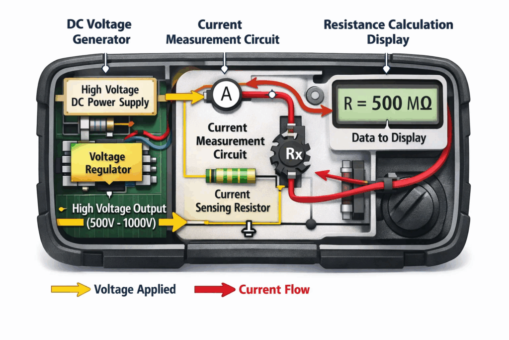
The Megger instrument operates on a deceptively simple yet highly effective principle. When you connect the test leads to your equipment and initiate the test, the device performs three simultaneous functions that reveal insulation integrity.
First, voltage generation: The Megger generates a stable, controlled DC voltage output. Unlike AC voltage found in standard power systems, DC voltage provides a consistent, unidirectional stress on insulation materials, making it ideal for detecting weaknesses. Modern digital Meggers offer selectable test voltages—250V, 500V, 1000V, 2500V, or 5000V—allowing technicians to match the test voltage to the equipment’s operating voltage rating.
Second, current measurement: As the test voltage is applied across the insulation, a tiny leakage current flows through imperfections, moisture, contamination, or degraded insulation material. The Megger’s sensitive circuitry measures this minute current with precision, typically in microamperes or nanoamperes.
Third, resistance calculation: Using Ohm’s Law (R = V/I), the instrument calculates insulation resistance by dividing the applied voltage by the measured leakage current. This calculation yields a resistance value displayed in megohms (MΩ) or gigohms (GΩ) on the instrument’s screen.
Advanced Meggers include additional features:
Understanding the difference between Megger and surge test for windings helps you select the right testing method for specific diagnostic requirements.

Successful Megger testing requires more than just the testing instrument itself. Professional technicians assemble a complete testing kit that ensures accurate measurements, personal safety, and proper documentation. Here’s your comprehensive equipment checklist:
Primary Testing Equipment:
Safety and Documentation Tools:
Optional but Recommended:
Professional facilities performing high voltage testing regularly maintain calibrated testing equipment to ensure measurement accuracy and regulatory compliance.

Proper preparation is absolutely critical for obtaining accurate Megger test results and ensuring personnel safety. Skipping or rushing through preparation steps accounts for most testing errors and dangerous incidents. Follow this systematic preparation protocol:
Step 1: System De-Energization (Non-Negotiable)
Before approaching any equipment for Megger testing, implement a comprehensive lockout/tagout procedure. Disconnect all power sources, including main feeds, control circuits, and backup supplies. Verify zero-energy state using a voltage detector at multiple points. Remember: Megger testing applies high voltage, and any residual voltage can damage the instrument or cause dangerous feedback.
Step 2: Equipment Disconnection
Physically disconnect the equipment under test from all external connections:
Step 3: Discharge Stored Energy
Electrical equipment stores energy even after de-energization. Motors, cables, and capacitive equipment retain charge that must be safely discharged:
Step 4: Terminal Cleaning and Inspection
Clean insulation and terminals thoroughly to remove:
Use isopropyl alcohol and lint-free cloths for cleaning. Contaminated surfaces create false low-resistance readings that mask actual insulation condition.
Step 5: Visual Inspection
Before testing, conduct a thorough visual examination:
Step 6: Environmental Assessment
Record environmental conditions that affect insulation resistance:
When checking windings on 3-phase motors, proper preparation ensures you detect actual insulation problems rather than measurement artifacts.
Now that your equipment is properly prepared, follow this detailed procedure for conducting accurate Megger tests. This methodology follows IEEE 43-2013 standards for rotating machinery and applies similarly to cables, transformers, and switchgear.
Step 1: Select Appropriate Test Voltage
Choose test voltage based on equipment rated voltage:
General rule: Test voltage should be approximately equal to or slightly higher than the equipment’s rated operating voltage.
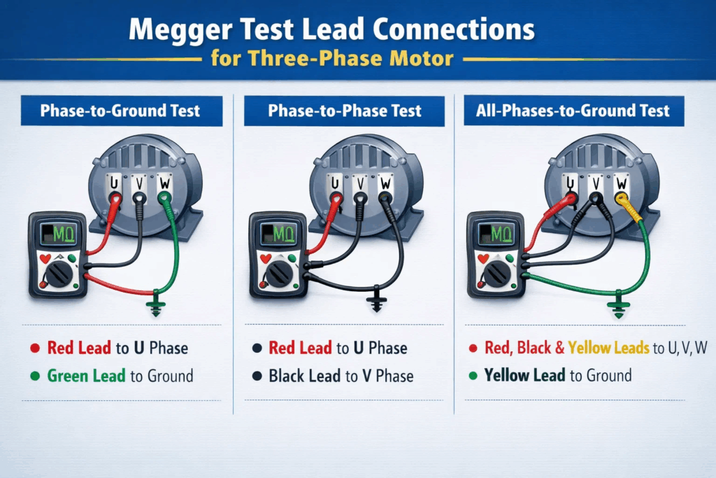
Step 2: Connect Test Leads Properly
Different types of equipment require specific connection configurations:
For Three-Phase Motors:
For Single-Phase Motors:
For Cables:
Step 3: Apply Test Voltage and Timing
Press the test button to apply voltage. For standard insulation resistance measurement:
Hold the test voltage steady for the entire duration. Modern digital Meggers maintain constant voltage automatically and display continuously updated resistance readings.
Step 4: Record and Interpret Results
Document all readings systematically:
Standard acceptance criteria:
Step 5: Calculate Diagnostic Ratios (Advanced Testing)
For motors and generators requiring deeper analysis:
Polarization Index (PI) = (R at 10 minutes) / (R at 1 minute)
Dielectric Absorption Ratio (DAR) = (R at 60 seconds) / (R at 30 seconds)
Step 6: Discharge Equipment After Testing
Critical safety step: After completing Megger testing, the insulation retains a significant electrical charge that must be safely discharged:
Understanding how to test motor windings comprehensively requires mastering both Megger and complementary testing techniques.
Interpreting Megger test results requires understanding both absolute resistance values and trending patterns over time. A single test provides a snapshot, but comparing results across time reveals insulation health trajectories that guide maintenance decisions.
Absolute Resistance Interpretation:
High Resistance (>100 MΩ): Indicates excellent insulation condition. New or well-maintained equipment typically shows readings in the hundreds or thousands of megohms. This represents minimal leakage current and healthy insulation materials.
Moderate Resistance (10-100 MΩ): Acceptable for many applications, though trending should be monitored. Equipment in humid environments or with moderate age may stabilize in this range. Continue quarterly monitoring to detect downward trends.
Low Resistance (1-10 MΩ): Caution zone requiring immediate investigation. While technically above minimum standards for some equipment, this range suggests developing problems—moisture absorption, contamination, or aging degradation. Schedule cleaning, drying, or detailed inspection.
Critical Resistance (<1 MΩ): Equipment should not be energized until repaired or replaced. Readings below 1 megohm indicate severe insulation compromise presenting shock hazards and fire risks. Implement immediate corrective action.
Trending Analysis: The Real Power of Megger Testing
Smart maintenance programs track insulation resistance over time, creating baseline values and trend lines:
Stable Trend: Resistance values remain relatively constant across multiple tests (within 20% variance). Indicates healthy insulation properly protected from environmental stresses. Continue routine testing intervals.
Gradual Decline: Resistance decreases steadily over months or years (10-30% annually). Suggests normal aging or progressive contamination. Plan cleaning, drying, or rewind before reaching critical thresholds.
Sudden Drop: Resistance falls sharply between tests (>50% decrease). Red flag indicating specific event—water ingress, mechanical damage, severe overheating, or chemical contamination. Requires immediate investigation and likely repair.
Temperature Correction Factor:
Insulation resistance is highly temperature-dependent, typically halving for every 10°C temperature increase. When comparing readings taken at different temperatures, apply correction factors:
Corrected Resistance = Measured Resistance × 2^[(T2-T1)/10]
Where T1 is reference temperature (typically 40°C) and T2 is test temperature.
Facilities performing both Megger and surge testing gain comprehensive insulation analysis, as each method detects different failure modes.
Megger testing involves high voltages that can cause serious injury or death if proper safety protocols are ignored. Every technician must understand and implement comprehensive safety measures throughout the testing process.
Electrical Hazards and Controls:
High Voltage Exposure Risk: Megger instruments generate up to 5,000V DC, sufficient to cause fatal electric shock. Never touch test leads, equipment terminals, or conductive surfaces while testing is active. Always assume test points are energized during and immediately after testing.
Stored Charge Danger: Insulation acts as a capacitor, storing electrical charge during testing. This stored energy can discharge violently through anyone contacting the equipment. Always discharge equipment for minimum 4× test duration after testing completion before touching terminals.
Inadvertent Energization: Despite lockout/tagout procedures, human error or miscommunication can result in equipment being energized during testing. Triple-verify zero-energy state before beginning work. Use personal LOTO devices that only you can remove.
Mandatory PPE Requirements:
Pre-Test Safety Verification Checklist:
✓ Equipment completely de-energized and LOTO applied
✓ All personnel notified of testing in progress
✓ Testing area barricaded if necessary
✓ No unauthorized personnel in testing zone
✓ Weather conditions safe (no rain during outdoor testing)
✓ Test equipment inspected and calibration current
✓ Emergency contact information accessible
✓ First aid kit and AED location known
During Testing Safety Protocols:
Emergency Response Preparation:
Know the emergency procedures before beginning any test:
Many electrical testing errors stem from inadequate safety preparation rather than technical mistakes. Never compromise on safety protocols.
Understanding where Megger testing fits within the broader insulation testing toolbox helps you select appropriate methods for specific diagnostic needs. Each testing technique reveals different aspects of insulation health.
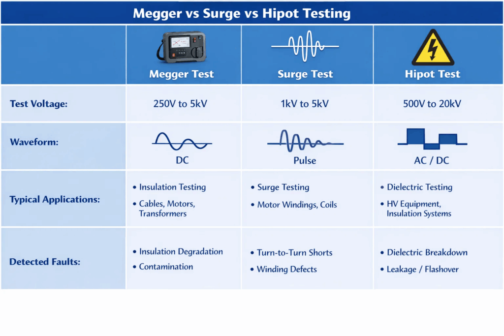
Megger Test vs. Surge Test:
While both evaluate insulation, they target different failure modes:
Megger Testing:
Surge Testing:
Best practice: Use Megger testing for routine maintenance, employ surge testing when Megger results are borderline or when turn-to-turn faults are suspected. The surge tester vs hipot tester comparison reveals additional testing method distinctions.
Megger Test vs. Hipot Test:
Both apply high voltage to insulation, but serve different purposes:
Megger Testing:
Hipot (High Potential) Testing:
Understanding what hipot testing entails and choosing between AC hipot vs DC hipot methods depends on equipment type and testing objectives.
Megger Test vs. Multimeter Resistance Measurement:
Standard multimeters appear to measure resistance, but cannot assess insulation:
Multimeter (Ohmmeter):
Megger:
Complementary Testing Strategy:
Professional maintenance programs implement multiple testing methods:
This layered approach catches failures at earliest possible stages, minimizing unplanned downtime.

Even experienced technicians occasionally make errors that compromise test accuracy or safety. Recognizing these common pitfalls helps you avoid them and obtain reliable results consistently.
Mistake #1: Testing Energized Equipment
Why it’s problematic: Connecting a Megger to energized equipment can destroy the instrument, damage the equipment under test, and cause serious injury or death.
Prevention: Always verify zero-energy state using multiple methods—check circuit breakers, use voltage detector, verify LOTO in place. If any doubt exists about de-energization, consult electrical schematics and senior technicians before proceeding.
Mistake #2: Inadequate Disconnection
Why it’s problematic: Leaving external connections attached creates parallel resistance paths that falsely lower readings. A motor connected to its control circuit, for example, might test through PLCs, soft starters, or VFDs, yielding meaningless results.
Prevention: Physically disconnect ALL external connections—power cables, control wiring, sensors, and grounding. Test only the equipment itself. Tag disconnected cables for proper reconnection.
Mistake #3: Testing on Contaminated Surfaces
Why it’s problematic: Surface contamination—dust, oil, moisture, carbon tracking—creates conductive paths that produce artificially low resistance readings. You might condemn perfectly good insulation based on surface conditions rather than true insulation health.
Prevention: Clean terminals and insulation surfaces thoroughly before testing. Use isopropyl alcohol and lint-free cloths. Allow surfaces to dry completely. Repeat cleaning if initial reading seems suspiciously low, then retest.
Mistake #4: Ignoring Temperature Effects
Why it’s problematic: Insulation resistance decreases dramatically with temperature. A motor tested immediately after operation might show 5 MΩ, while the same motor tested cold could read 50 MΩ. Comparing readings at different temperatures leads to false conclusions about insulation degradation.
Prevention: Record temperature during every test. Allow equipment to stabilize at ambient temperature (ideally overnight) before testing. Apply temperature correction factors when comparing readings taken at different temperatures.
Mistake #5: Using Incorrect Test Voltage
Why it’s problematic: Testing with voltage too low may not adequately stress insulation to reveal defects. Testing with voltage too high can damage sensitive electronic components or breakdown already-weakened insulation.
Prevention: Follow the voltage selection rule: test voltage approximately equal to equipment rated voltage. For equipment with electronic controls, verify whether components can tolerate test voltage or if they require disconnection.
Mistake #6: Insufficient Test Duration
Why it’s problematic: Insulation resistance often increases during the first minute of testing (dielectric absorption). Taking only instant readings might show false low values. Conversely, failing to hold test voltage long enough prevents proper PI calculation.
Prevention: Always maintain test voltage for minimum 60 seconds for standard measurements. For PI testing on motors above 1HP, hold for full 10 minutes. Modern digital Meggers display continuously updated readings.
Mistake #7: Failing to Discharge Equipment
Why it’s problematic: This is the most dangerous error. Insulation stores charge like a capacitor during testing. Touching uncharged equipment can cause violent shock, potentially fatal.
Prevention: After every test, discharge equipment for minimum 4× test duration. Use Megger’s built-in discharge function or apply temporary grounding. Verify zero voltage before touching any conductors. Never assume equipment has discharged on its own.
Mistake #8: Not Documenting Results Properly
Why it’s problematic: Without comprehensive documentation, trending analysis becomes impossible. You cannot determine whether readings represent normal operation, gradual degradation, or sudden failure. Maintenance decisions become guesswork rather than data-driven analysis.
Prevention: Maintain detailed test records including:
Mistake #9: Testing During Inappropriate Conditions
Why it’s problematic: Testing during rain, high humidity, or condensation conditions yields unrealistically low readings. These readings don’t represent equipment condition under normal operating environments.
Prevention: Postpone testing if relative humidity exceeds 85%, if visible moisture or condensation exists, or during/immediately after precipitation. For outdoor equipment, test during dry, stable weather periods.
Mistake #10: Relying Solely on Single Pass/Fail Criteria
Why it’s problematic: Viewing Megger testing as simply pass/fail misses the test’s real value—trend analysis and predictive capability. Equipment reading 2 MΩ today might be acceptable, but if last month’s reading was 20 MΩ, a significant problem exists despite passing minimum criteria.
Prevention: Always compare current readings against historical baseline and trends. Investigate any reading showing >25% change from previous test. Focus on rate of change, not just absolute values.
When testing windings on single-phase motors, applying proper technique eliminates these common errors and produces reliable diagnostic information.
Test critical production motors quarterly to establish trending patterns. Non-critical motors can be tested semi-annually or annually. Always test immediately after repairs, moisture exposure, or electrical events. IEEE 43-2013 recommends annual testing as minimum, but high-reliability facilities test more frequently for meaningful trending data.
Properly performed Megger testing at appropriate voltages is non-destructive. However, electronic components like VFDs, PLCs, and soft starters can be damaged by high test voltages. Always disconnect sensitive electronics before testing or consult manufacturer guidelines. When uncertain, start with lower test voltages and increase gradually.
The standard minimum is 1 megohm plus 1 megohm per 1000 volts of operating voltage. For example, a 480V motor requires minimum 1.48 MΩ. However, best practice suggests resistance should exceed minimum by factor of 10 or more. Motors testing near minimum values should be cleaned, dried, or scheduled for rewind.
As temperature increases, molecular motion in insulation materials increases, providing more pathways for electron movement and reducing resistance. The general rule: resistance halves for every 10°C temperature increase. This is why temperature documentation and correction factors are essential for accurate trending and comparison of test results taken at different times.
Multimeters apply very low voltage (0.2-9V) suitable for measuring conductor resistance but cannot stress insulation adequately. Megger instruments apply high voltage (250V-5000V) necessary to reveal insulation weaknesses under operational conditions. While multimeters measure up to 40 MΩ typically, Meggers measure thousands of megohms. They serve complementary but different purposes.
If resistance dropped >50% suddenly, stop using equipment immediately and investigate the cause. For gradual decline over months: clean equipment thoroughly, bake out moisture per manufacturer procedures, inspect for physical damage, then retest. If resistance improves significantly after cleaning, resume operation with increased monitoring. If resistance remains low or continues declining, schedule rewind or replacement.
Never test motors while connected to VFDs or soft starters—high test voltage will damage sensitive electronics. Always physically disconnect the motor from drive electronics before testing. Test motor insulation separately from the drive. Some modern VFDs include built-in insulation monitoring that eliminates separate Megger testing needs. Consult drive manufacturer for specific recommendations.
Spot reading is a single resistance measurement at a specific time point (typically 60 seconds), providing a snapshot for pass/fail assessment. Polarization Index (PI) is a ratio comparing resistance at 10 minutes to resistance at 1 minute. PI reveals insulation quality more reliably because it measures how insulation absorbs test voltage over time. Good insulation shows PI > 2.0, while contaminated insulation shows PI < 1.5.
Megger testing remains the most reliable method for assessing electrical insulation health and preventing costly equipment failures. By regularly measuring insulation resistance, you gain early warning of deterioration before it leads to catastrophic breakdowns, production stoppages, or safety hazards.
The key to successful Megger testing lies in consistency—establish baseline measurements, test at regular intervals, and track trending data over time. This predictive approach transforms maintenance from reactive firefighting to proactive asset management.
Invest in quality testing equipment, train your technicians thoroughly, maintain detailed records, and most importantly, act on the data you collect. The few minutes spent performing proper Megger tests can save hours of unplanned downtime and prevent equipment damage that costs thousands to repair. Start implementing quarterly Megger testing today—your equipment reliability and operational safety depend on it.
Ready to enhance your electrical testing program?
Explore reliable surge testers and high-voltage testing equipment from Vivid Metrawatt Global to improve fault detection and protect your assets: