90% of motor failures go undetected by traditional testing methods like multimeters and megohmmeters, leading to unexpected downtime costing thousands per hour. Relying solely on insulation-to-ground testing misses developing winding faults, connection problems, and rotor defects until catastrophic failure occurs. Motor Circuit Analysis provides comprehensive de-energized evaluation detecting electrical imbalances, insulation degradation, and cable faults all in under three minutes without applying destructive high voltages.
Motor Circuit Analysis (MCA) is a de-energized, low-voltage testing methodology that comprehensively evaluates the electrical health of motors, cables, and connections without requiring motor operation or destructive high-voltage application. Unlike traditional testing focusing solely on insulation-to-ground resistance, MCA assesses the complete motor system electrical characteristics.
Key characteristics of MCA:
The technology emerged in the mid-1980s when reliability engineers recognized traditional testing methods—continuity checks, megohmmeter readings, and basic resistance measurements—identified only 10% of motor failures before they occurred. Motor winding failures typically begin with turn-to-turn insulation breakdown invisible to ground-fault testing, progressing silently until catastrophic failure.
MCA’s fundamental advantage: By applying low-voltage sinusoidal signals and measuring how motor circuits respond, MCA identifies electrical imbalances and insulation degradation long before visible symptoms appear. The technique evaluates entire motor systems—not just individual components—revealing problems in cables, connections, stator windings, and even rotor circuits through electromagnetic coupling.
For facilities implementing predictive maintenance programs, MCA provides quantitative baseline measurements enabling trending analysis. As insulation degrades or connections deteriorate, measured values shift from baseline references, triggering maintenance action before failure occurs.
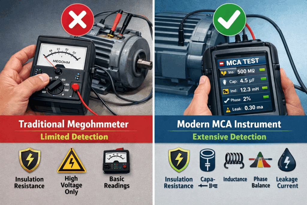
Understanding how Motor Circuit Analysis compares to conventional testing clarifies its unique diagnostic capabilities:
Megohmmeter limitations: Insulation resistance testing exclusively detects ground faults—current leakage paths between windings and motor frame. While valuable, ground faults represent only a fraction of motor failures. Most winding degradation begins with turn-to-turn insulation breakdown, which megohmmeters cannot detect until shorts progress to involve ground paths.
MCA advantages: Evaluates phase-to-phase winding relationships detecting turn-to-turn faults, coil-to-coil problems, and phase imbalances invisible to ground testing. Identifies developing issues months before ground-fault symptoms manifest.
Multimeter limitations: Basic resistance measurements with multimeters provide crude assessment of winding continuity and approximate balance. However, static DC resistance cannot reveal inductive or capacitive circuit characteristics, nor can it detect subtle asymmetries indicating developing faults.
MCA advantages: Uses AC test signals revealing complete circuit behavior including resistance, reactance, and phase relationships. Detects impedance imbalances from contamination, overheating, or partial shorts that DC measurements miss entirely.
While surge testing excels at detecting turn-to-turn insulation weaknesses, it requires applying high voltages (2-4× operating voltage) that can potentially damage compromised insulation. Surge testing provides valuable diagnostic information but carries risk when troubleshooting suspect motors.
MCA advantages: Non-destructive low-voltage approach safe for testing motors in unknown condition. Can be performed repeatedly without insulation stress, making it ideal for predictive maintenance trending. Detects many of the same faults surge testing identifies but through different measurement principles.
Complementary approach: Leading maintenance programs combine MCA for routine monitoring with periodic surge testing for comprehensive insulation integrity verification. Understanding how to test motor windings using multiple methods provides complete diagnostic coverage.
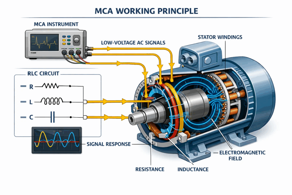
Motor Circuit Analysis operates on fundamental electrical principles—resistance, inductance, and capacitance—that define three-phase motor circuit behavior. Understanding the complete working mechanism helps maintenance professionals appreciate MCA’s diagnostic power.
Every three-phase motor contains three RLC circuits (Resistance-Inductance-Capacitance networks) corresponding to each phase winding. These circuits exhibit specific electrical behaviors when energized.
Resistance (R): Opposes current flow, converting electrical energy to heat. Measured in ohms, resistance depends on:
Inductance (L): Stores energy in magnetic fields surrounding current-carrying conductors. Measured in henries, inductance depends on:
Capacitance (C): Stores energy in electric fields between conductors separated by insulation. Measured in farads, capacitance depends on:
Step 1: Signal Generation
MCA instruments generate precise low-voltage AC signals—typically ranging from 2 to 9 volts—with pure sinusoidal waveforms. These signals sweep across multiple frequencies, commonly from 100 Hz to 800 Hz, to excite different aspects of the motor’s electrical characteristics.
The low voltage ensures complete safety. Unlike high voltage testing that can stress or damage insulation, MCA signals cannot harm even severely degraded windings. The current levels remain minuscule—typically milliamperes—insufficient to create significant magnetic forces or heating.
Step 2: Signal Application
Test signals are applied to motor terminals in specific patterns:
For three-phase motors, the instrument typically applies signals phase-to-phase (Line 1 to Line 2, Line 2 to Line 3, Line 3 to Line 1) and phase-to-ground. This comprehensive testing pattern reveals both winding-to-winding characteristics and insulation-to-ground integrity.
Step 3: Response Measurement
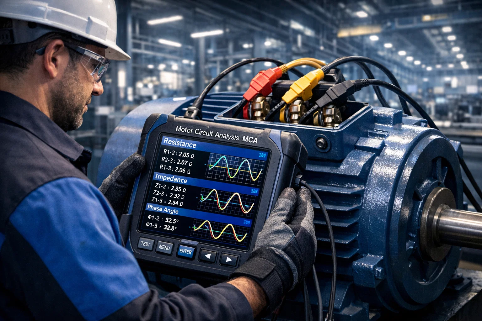
As AC signals flow through motor circuits, the instrument simultaneously measures:
Voltage across the circuit: The applied test voltage Current through the circuit: The resulting current flow Phase relationship: Time delay between voltage and current waveforms Frequency response: How impedance changes with signal frequency
These measurements occur thousands of times per second, with digital signal processing averaging results to eliminate noise and ensure accuracy.
Step 4: Parameter Calculation
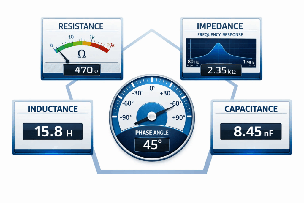
From raw voltage and current measurements, the MCA instrument calculates fundamental electrical parameters:
Resistance (R) = Voltage / Current when measured with DC or very low-frequency AC
Impedance (Z) = Voltage / Current when measured with AC at specific frequency
Inductance (L) calculated from impedance and frequency using: L = (Z² – R²)^0.5 / (2πf)
Phase Angle (θ) measured as time shift between voltage and current, expressed in degrees
Capacitance (C) derived from impedance characteristics at different frequencies
In properly functioning three-phase motors, electrical symmetry exists between phases. When MCA applies identical test signals to each phase:
Expected behavior:
This symmetry reflects identical coil construction—same number of turns, same wire gauge, same insulation thickness, same physical geometry. The motor behaves as three parallel electrical paths with matched characteristics.
Motor defects break natural symmetry, creating measurable electrical imbalances:
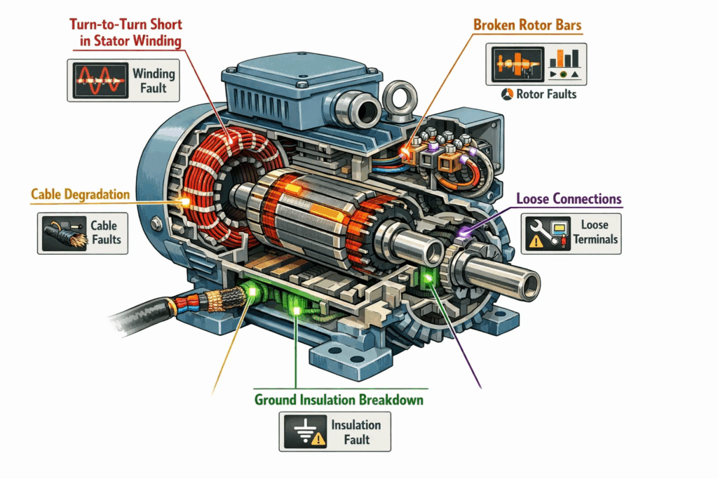
Turn-to-Turn Short Example:
When insulation fails between adjacent turns in a single coil:
The MCA instrument detects these changes instantly. While healthy phases show phase angles of 85°, the faulted phase might drop to 78-80°, triggering alarms.
Connection Resistance Example:
Loose or corroded terminal connections increase resistance:
MCA identifies the specific phase with elevated resistance, directing technicians to the exact problem location.
Ground Insulation Breakdown Example:
When insulation between windings and motor frame degrades:
MCA’s sophisticated capability extends beyond stator windings to rotor evaluation through mutual inductance—one of the most remarkable aspects of the technology.
The Physical Principle:
When AC test signals energize stator windings, they create time-varying magnetic fields that penetrate the rotor. According to Faraday’s Law of electromagnetic induction, these changing magnetic fields induce voltages in rotor conductors (squirrel cage bars or wound rotor coils).
Induced rotor currents: The voltages induced in rotor circuits cause currents to flow, creating secondary magnetic fields. These rotor-generated fields interact with the original stator fields, altering the stator’s effective inductance and impedance.
Rotor Fault Detection Mechanism:
Healthy rotor condition: Symmetrical rotor bar construction creates balanced electromagnetic coupling with all three stator phases. The mutual inductance effect distributes evenly, maintaining phase balance in stator measurements.
Broken rotor bars: Fractured bars cannot carry induced currents. The affected rotor section creates electromagnetic asymmetry. Stator phases coupling most strongly with the broken bar region show altered inductance and impedance compared to other phases.
Cracked end rings: End rings electrically connect rotor bars. Cracks isolate bar sections, creating electromagnetic dead zones. The asymmetrical rotor field modulates stator measurements, appearing as phase imbalances during MCA testing.
Detection sensitivity: Modern MCA instruments detect rotor problems through statistical analysis of measurements captured during manual shaft rotation (dynamic testing). As the shaft rotates, different rotor sections align with stator poles. Healthy rotors show consistent measurements regardless of position. Faulty rotors create position-dependent variations revealing the problem.
Advanced MCA systems employ multi-frequency testing, applying signals from 100 Hz to 800 Hz. Different frequencies emphasize different circuit characteristics:
Low frequencies (100-200 Hz): Emphasize inductive effects, revealing winding turn counts and inductance asymmetries
Mid frequencies (300-500 Hz): Balance resistive, inductive, and capacitive effects, providing comprehensive circuit characterization
High frequencies (600-800 Hz): Emphasize capacitive effects, revealing insulation system condition and contamination
By analyzing how impedance, phase angle, and current change across frequency ranges, MCA creates electrical fingerprints uniquely identifying fault types. Similar to how waveform analysis in surge testing reveals specific fault signatures, MCA’s frequency response analysis pinpoints problem sources with high accuracy.
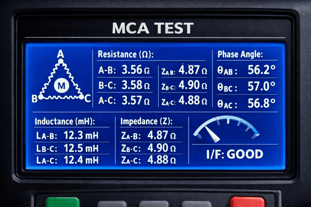
Imagine testing a 100 HP three-phase motor at 480V:
Test initiation: Technician connects MCA instrument to motor terminals after de-energization and lockout
Automated sequence begins:
Result analysis: Phase L3 shows elevated impedance and reduced phase angle compared to L1 and L2. This pattern indicates developing turn-to-turn short in L3 winding.
Diagnostic conclusion: The phase angle reduction (85° → 78°) suggests insulation degradation allowing current leakage between turns. The short hasn’t progressed to complete turn failure (which would reduce impedance), but insulation breakdown is active and worsening.
Recommended action: Increase monitoring frequency, plan motor rewind during next scheduled outage within 3-6 months, investigate operating conditions accelerating insulation degradation.
This complete understanding of how Motor Circuit Analysis works—from fundamental electrical principles through practical fault detection—enables maintenance teams to confidently interpret results and make informed maintenance decisions. For comprehensive motor evaluation, combining MCA with automated motor testing systems provides maximum diagnostic capability across all failure modes.
Motor Circuit Analysis instruments capture multiple electrical parameters revealing different aspects of motor condition:
DC Resistance: Fundamental measurement of conductor opposition to direct current flow. Expressed in ohms or milliohms, resistance identifies:
Phase balance assessment: Healthy three-phase motors show resistance balance within 2-5% between phases. Greater variations indicate manufacturing defects or developing problems.
AC Impedance: Total opposition to alternating current including both resistive and reactive components. Measured in ohms at specific frequencies, impedance reveals:
Frequency-dependent behavior: MCA instruments measure impedance at multiple frequencies, creating impedance profiles revealing how circuits respond across the frequency spectrum. Abnormal frequency responses indicate specific fault types.
Magnetic Energy Storage: Inductance quantifies winding magnetic field strength for given current. Measured in henries or millihenries, inductance identifies:
Important consideration: While inductance measurements provide valuable information, MCA doesn’t rely solely on inductance for fault detection. Many motor designs inherently exhibit inductance imbalances due to construction geometry, potentially causing false alarms if interpreted without context.
Voltage-Current Relationship: Phase angle measures the time relationship between applied voltage and resulting current in AC circuits. Expressed in degrees, phase angle reveals:
Detection sensitivity: Phase angle measurements provide exceptional sensitivity to developing winding shorts. Even single-turn shorts create detectable phase angle shifts, enabling early fault identification before resistance or inductance changes become measurable.
Advanced Diagnostic Parameter: Some MCA systems employ sophisticated current/frequency response analysis measuring how circuit current varies with applied signal frequency. This parameter:
Combined with phase angle analysis, current/frequency response delivers highly accurate fault detection distinguishing genuine problems from inherent design characteristics.
Understanding these parameters helps technicians performing three-phase motor winding checks interpret MCA results accurately and make informed maintenance decisions.
Motor Circuit Analysis encompasses both de-energized and energized testing methodologies, each serving distinct diagnostic purposes:
The traditional and most common MCA application involves testing motors while completely de-energized and disconnected from power supplies.
Testing approach: Technician connects MCA instrument to motor terminals at the Motor Control Center or directly at the motor. Low-voltage AC signals pass through windings, cables, and connections. Instrument measures resistance, impedance, inductance, phase angle, and insulation resistance.
Capabilities:
Advantages:
Limitations:
Online Motor Circuit Analysis monitors operating motors, analyzing current and voltage signatures revealing both electrical and mechanical conditions.
Current Analysis Focus: Examines current waveforms identifying:
Voltage Analysis Focus: Evaluates supply voltage characteristics detecting:
Integration approach: Advanced facilities implement both offline and online MCA in complementary programs. Quarterly offline testing establishes baseline electrical characteristics and detects developing winding faults. Continuous or monthly online monitoring tracks mechanical condition and power quality, triggering offline investigation when anomalies appear.
This comprehensive strategy provides complete motor health visibility, addressing both electrical and mechanical failure modes through appropriate testing methodologies.
Motor Circuit Analysis identifies numerous electrical and mechanical defects through direct measurement or indirect electromagnetic coupling:
Turn-to-Turn Shorts: Most common winding failure mode begins with insulation breakdown between adjacent turns in the same coil. MCA detects these faults early through:
Coil-to-Coil Shorts: Insulation failure between different coils in the same phase or between phases. Detected through severe phase imbalance and dramatically altered electrical characteristics.
Phase Imbalance: Asymmetrical electrical properties between phases indicating:
Ground Faults: While megohmmeters excel at ground fault detection, MCA provides the same capability alongside comprehensive phase-to-phase evaluation, eliminating the need for multiple test instruments.
High-Resistance Connections: Loose, corroded, or pitted contacts create resistance increases detected through:
Cable Degradation: Insulation breakdown in motor cables manifests as:
Contamination: Oil, moisture, carbon dust, or chemical contamination on windings alters electrical properties detectable through MCA measurements.
Broken Rotor Bars: Fractured aluminum or copper rotor bars detected through mutual inductance effects creating asymmetrical stator measurements.
Cracked End Rings: End ring fractures electrically isolating rotor bar sections, detected similarly to broken bars.
Casting Voids: Manufacturing defects or porosity in die-cast rotors create electromagnetic asymmetries detectable during static MCA testing.
Incorrect Turn Counts: Assembly errors or repair mistakes creating wrong coil turn numbers detected through phase imbalance.
Reversed Coils: Coil groups wound or connected in wrong direction creating severe electrical asymmetry.
Wrong Wire Gauge: Using incorrect conductor size during repairs detected through resistance and impedance variations.
Regular application of MCA alongside traditional methods provides comprehensive coverage detecting virtually all electrical motor failure modes. For motors showing suspicious MCA results, follow-up investigation ensures proper fault characterization.

Implementing effective Motor Circuit Analysis programs requires systematic procedures ensuring accurate, repeatable measurements:
Safety First:
Documentation:
Connection Verification:
Advantage of MCC testing: Evaluates entire motor system—cables, connections, and motor—in single test session, identifying whether problems exist upstream or in the motor itself.
Step 1: Initial Test
Step 2: Fault Localization
Step 3: Documentation
When to test at motor: Troubleshooting known problems, commissioning newly installed motors, quality control after repairs, or when MCC testing reveals motor-specific issues.
Procedure:
DC Motor Testing: Requires bar-to-bar analysis using commutator segments. Test between adjacent commutator bars while manually rotating armature, creating profile revealing turn-to-turn balance.
Single-Phase Motor Testing: Follow specialized procedures accounting for start winding and run winding differences. Refer to single-phase motor testing guidelines for detailed methodology.
Synchronous Motor Testing: Perform both static tests (stationary shaft) and dynamic tests (manual rotation) to separately evaluate stator, field windings, and amortisseur windings.
Implementing MCA testing programs delivers quantifiable advantages across maintenance, reliability, and operational performance:
MCA identifies developing problems 6-12 months before conventional methods, providing critical lead time for:
Quantified value: Studies show MCA detects faults 3-6 months earlier than vibration analysis for electrical problems, enabling proactive maintenance preventing unexpected downtime.
Unlike testing methods targeting specific failure modes, MCA evaluates entire motor systems revealing problems anywhere in the electrical path:
Efficiency advantage: Single 3-minute test provides information requiring multiple instruments and 15-20 minutes using traditional methods.
Low-voltage MCA safely tests motors in unknown condition without risk of damaging compromised insulation. This capability proves invaluable for:
Contrast to surge testing: While digital surge testers provide valuable diagnostics, they apply high voltages potentially damaging weak insulation. MCA offers preliminary screening identifying motors requiring detailed investigation before applying stress testing.
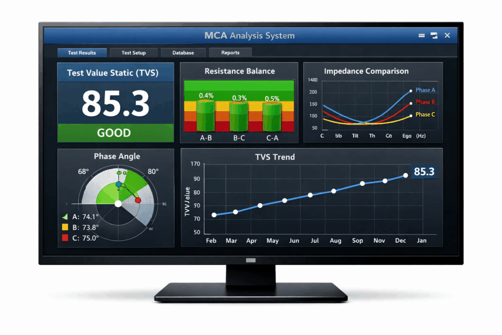
MCA instruments generate quantitative measurements—Test Value Static (TVS), resistance, impedance, phase angle—enabling statistical trending analysis. Maintenance teams establish:
Implementation of predictive maintenance: Track TVS over time for critical motors. When current TVS exceeds 3% of reference value, motor condition has changed significantly, warranting detailed evaluation and potential repair planning.
MCA testing requires minimal training—entry-level technicians successfully operate instruments after brief instruction. Capital investment remains modest compared to comprehensive vibration analysis systems, yet detection capabilities exceed traditional electrical testing by 40-50%.
Return on investment: Facilities report payback periods of 6-12 months after preventing single critical motor failure. For plants with extensive motor populations, MCA proves essential for maximizing uptime while optimizing maintenance resources.
For organizations seeking comprehensive motor reliability, combining MCA with complementary technologies like EV motor testing methodologies creates robust diagnostic programs addressing all failure modes across motor types and applications.
Modern Motor Circuit Analysis instruments incorporate advanced electronics and sophisticated algorithms optimizing measurement accuracy and diagnostic capability:
Signal Generation: MCA instruments produce precise low-voltage sinusoidal AC signals at multiple frequencies. Signal purity matters—any harmonic distortion corrupts measurements. Quality instruments maintain <1% total harmonic distortion ensuring measurement validity.
High-Resolution Measurement: Capturing subtle electrical variations requires:
Digital Signal Processing: Modern instruments employ DSP techniques eliminating noise, averaging multiple measurements, and extracting relevant parameters from raw voltage-current waveforms.
Automated Analysis: Contemporary MCA instruments incorporate:
Fault Localization: Software guides technicians through systematic testing procedures isolating faults to specific circuit sections—cables vs. connections vs. motor windings.
Data Management: Cloud-connected instruments enable:
Portable Handheld Units: Battery-powered instruments for field testing, troubleshooting, and spot-checking motor condition. Ideal for electricians responding to failures or performing routine preventive maintenance.
Permanently Installed Systems: Dedicated MCA instruments continuously or periodically testing critical motors, automatically logging results and generating alerts when conditions deteriorate.
Integrated Test Systems: Comprehensive motor diagnostic platforms combining MCA with additional capabilities—power quality analysis, vibration monitoring, thermal imaging integration—providing complete equipment health assessment.
Understanding troubleshooting of electrical testing errors ensures maintenance teams properly operate MCA equipment and interpret results accurately, avoiding false positives while catching genuine developing faults.
Optimal Motor Circuit Analysis deployment encompasses multiple application scenarios:
Routine Monitoring Schedule:
Trending strategy: Establish baseline measurements upon installation or after repairs. Subsequent tests compare against baseline, with statistical alerts generated when measurements drift beyond acceptance limits.
Immediate testing scenarios:
Diagnostic advantage: MCA rapidly identifies electrical vs. mechanical problems, guiding subsequent investigation and preventing unnecessary motor removal when problems exist elsewhere in the system.
New motor acceptance: Test motors upon delivery before installation, establishing baseline reference values and detecting shipping damage or manufacturing defects before acceptance.
Post-repair verification: After motor rewinds or repairs, MCA confirms:
Installation commissioning: Test newly installed motors before energization, verifying:
Spare motor evaluation: Motors in long-term storage suffer insulation degradation from moisture absorption and chemical reactions. Periodic MCA testing identifies deteriorated units requiring refurbishment before emergency needs arise.
Refurbishment prioritization: Limited budgets require strategic motor repair decisions. MCA testing objectively identifies which stored motors warrant immediate attention versus those safely remaining in inventory.
Successful Motor Circuit Analysis requires understanding both quantitative measurements and qualitative patterns indicating specific fault types:
Many MCA instruments calculate proprietary TVS numbers representing overall motor condition based on multiple measurements processed through algorithms. TVS provides single-value assessment simplifying result interpretation:
TVS interpretation guidelines:
Critical threshold: TVS changes >3% from baseline indicate condition deterioration warranting investigation.
Healthy three-phase motors exhibit resistance symmetry between phases. Calculate resistance imbalance:
Elevated resistance: Indicates loose connections, corroded contacts, or different conductor sizes.
Reduced resistance: Suggests shorted turns or parallel current paths.
Balanced impedance: All three phases within 2-3% suggests healthy windings.
Single-phase impedance reduction: Indicates turn-to-turn short in that phase reducing total winding impedance.
Across-the-board impedance changes: Temperature effects (all phases increase or decrease together) or measurement issues.
Inductance interpretation caution: Many motor designs inherently show inductance imbalance due to construction geometry. Don’t rely solely on inductance for fault diagnosis—use in conjunction with phase angle and current/frequency response.
Phase angle provides sensitive fault detection for turn-to-turn shorts:
Normal phase angle: Typically 75-89 degrees for three-phase induction motors, varies with motor design.
Reduced phase angle: Single phase showing 5+ degree reduction suggests turn-to-turn short increasing capacitance.
Phase angle trend monitoring: Progressive angle reduction over multiple tests confirms developing fault, even when single measurement falls within normal range.
Motor design characteristics: Some concentric-wound and consequent-pole motors inherently exhibit phase imbalances. Compare suspicious motors to identical units establishing design-specific acceptance criteria.
Testing location effects: Measurements from MCC include cable and connection characteristics. Apparent motor problems may originate upstream—always retest at motor terminals before condemning motor.
Temperature influences: Resistance increases approximately 0.4% per degree Celsius. Motors tested at different temperatures show resistance variations unrelated to condition.
Rotor position effects: In motors with rotors installed, measurements can vary slightly with rotor position. Repeat tests with shaft rotated 120° confirming measurement consistency.
Ready to implement advanced motor diagnostics? Contact Vivid Metrawatt Global to discuss how Motor Circuit Analysis integrates with comprehensive motor testing solutions for maximum equipment reliability and uptime.
No, MCA cannot damage motor windings. The technology applies low-voltage AC signals (<9V) with minimal current—far below levels capable of insulation stress or winding heating. Unlike surge testing which applies high voltages potentially harmful to compromised insulation, MCA remains completely non-destructive even when testing motors in unknown condition. This safety characteristic enables unlimited testing frequency without cumulative insulation degradation.
Motor Circuit Analysis and Motor Current Signature Analysis are frequently confused due to identical acronyms. MCA is de-energized testing using low-voltage signals measuring resistance, impedance, inductance, and phase angle while motors are off. MCSA is online testing analyzing current waveforms from operating motors detecting mechanical problems like rotor defects, bearing issues, and misalignment. Both techniques complement each other—MCA excels at electrical fault detection while MCSA identifies mechanical and load-related problems.
MCA applies to virtually all motor types: three-phase AC induction motors (squirrel cage and wound rotor), single-phase motors, synchronous motors, DC motors (series, shunt, compound), servo motors, and generators. Testing methodology adapts to specific motor configurations, but fundamental measurement principles remain consistent. MCA works regardless of motor size, voltage rating, or power level—from fractional horsepower to multi-megawatt machines.
Standard predictive maintenance testing from the Motor Control Center requires approximately 3 minutes per motor including instrument connection, automated testing, and result documentation. Detailed troubleshooting or dynamic rotor testing may extend to 10-15 minutes. This efficiency enables testing large motor populations during scheduled maintenance windows without significant time investment, making MCA practical even for facilities with hundreds of motors.
Entry-level technicians successfully perform MCA testing after brief instruction—typically 2-4 hours covering instrument operation, safety procedures, and basic result interpretation. Advanced training (8-16 hours) develops expertise in detailed troubleshooting, complex motor types, and sophisticated result analysis. Unlike vibration analysis requiring extensive background in mechanical systems and signal processing, MCA’s automated analysis capabilities reduce training barriers enabling rapid program implementation.
Motor Circuit Analysis represents a paradigm shift in electrical motor diagnostics, providing comprehensive assessment detecting 90% of motor failures through quick, safe, non-destructive testing. By evaluating complete motor systems—windings, cables, connections, and even rotors through electromagnetic coupling—MCA identifies developing problems months before conventional methods, enabling proactive maintenance preventing costly unexpected failures.
The technology’s fundamental advantages—low-voltage safety, rapid testing speed, comprehensive fault coverage, and quantitative trending capability—make MCA indispensable for modern predictive maintenance programs. Facilities implementing MCA consistently report significant returns on investment through extended motor life, eliminated emergency repairs, optimized maintenance timing, and prevented production losses.
Integration with complementary diagnostic technologies creates comprehensive equipment reliability strategies. MCA handles electrical fault detection, vibration analysis monitors mechanical conditions, thermography identifies heat-related problems, and periodic surge testing verifies insulation integrity. This multi-technology approach ensures early detection regardless of failure mode, maximizing equipment availability while minimizing maintenance costs.
For maintenance teams committed to reliability excellence, Motor Circuit Analysis provides essential capability detecting the majority of motor failures conventional testing misses. The combination of technological sophistication and operational simplicity enables organizations of any size to implement effective programs, protecting motor investments and ensuring continuous process operation.
Combine Motor Circuit Analysis with advanced electrical testing solutions from Vivid Metrawatt Global to achieve full-spectrum motor diagnostics—from routine screening to deep fault characterization. Ensure compliance with NEMA and IEC standards while improving reliability, performance, and equipment life.