
Last updated: August 2026 · Reviewed by the Vivid Metrawatt engineering team, Mumbai
| Full form | SPD — Surge Protection Device (also: surge arrester, TVSS) |
| Core function | Diverts transient surge current to earth and clamps residual voltage |
| Governing standards | IEC 61643-11 (product), IEC 62305 (lightning protection), UL 1449 |
| Types | Type 1 (origin/service entry), Type 2 (sub-distribution), Type 3 (point of use) |
| Key ratings | Up, Uc, In, Imax, Iimp |
| Typical response time | <25 ns (MOV) · <1 ns (silicon avalanche diode) |
| Max connecting lead length | 0.5 m total (in + out) — longer leads add inductive voltage drop |
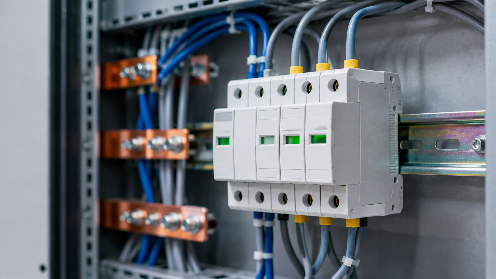
A surge protection device (SPD) is a protective component installed in an electrical panel that limits transient overvoltages by diverting surge current to earth. It clamps voltage spikes — from lightning, switching operations or utility faults — to a safe residual level, typically within 25 nanoseconds, before the spike reaches connected equipment.
A surge protection device is a non-linear voltage-limiting component wired in parallel with the load. Under normal conditions it presents extremely high impedance and passes almost no current. When voltage crosses its threshold, impedance collapses within nanoseconds and the device becomes a low-resistance path, shunting surge energy to the protective earth conductor.
The device does not absorb the surge. It redirects it — which is why earthing quality determines SPD performance more than the SPD’s own rating.
Where transients come from:
Industry field data consistently attributes only a minority of damaging transients to lightning; the majority originate inside the facility, from the plant’s own switching operations.
An SPD operates in three phases:
The physics is close to what happens in a surge generator used for winding tests: a capacitor bank discharges a fast-rising impulse into a load. The difference is intent — a surge generator creates the impulse deliberately to reveal insulation weakness, while an SPD suppresses it.
A critical, frequently ignored detail: every 1 metre of connecting lead adds roughly 1 kV of inductive voltage drop during a fast transient. An SPD rated U<sub>p</sub> = 1.5 kV installed with 1 m of loop wiring can deliver 2.5 kV or more to the load. Keep total lead length under 0.5 m and twist the conductors.
| Type 1 | Type 2 | Type 3 | |
|---|---|---|---|
| IEC class | Class I | Class II | Class III |
| Test waveform | 10/350 µs | 8/20 µs | 1.2/50 µs + 8/20 µs |
| Installation point | Service entrance / main LT panel | Sub-distribution board / MCC | At the equipment (socket, panel) |
| Protects against | Direct lightning current | Residual + switching surges | Local switching, final trim |
| Key rating | I<sub>imp</sub> (kA, 10/350) | I<sub>n</sub> / I<sub>max</sub> (kA, 8/20) | U<sub>oc</sub> (kV) |
| Typical use | Buildings with external LPS, substations | Industrial panels, MCCs, VFD feeders | PLCs, drives, instrumentation |
How they work together: Type 1 handles the bulk energy, Type 2 reduces what gets through, Type 3 provides final clamping. Coordinate them with a minimum 10 m of cable between stages (or a decoupling inductor) so the upstream device fires first.
For a plant with no external lightning protection system, a well-selected Type 2 SPD at the main panel plus Type 3 at sensitive drives is usually the correct, economical choice.
Most datasheet confusion comes from treating “kA” as the headline number. It isn’t.
| Rating | Meaning | Why it matters |
|---|---|---|
| U<sub>p</sub> — voltage protection level | Residual voltage let through | The single most important spec. Must sit below the equipment’s withstand (U<sub>w</sub>) |
| U<sub>c</sub> — max continuous operating voltage | Highest steady voltage the SPD tolerates | Too low → nuisance failure; too high → poor clamping |
| I<sub>n</sub> — nominal discharge current | Surge the SPD survives repeatedly (8/20 µs) | The realistic endurance figure |
| I<sub>max</sub> — max discharge current | Single-shot survival (8/20 µs) | Marketing-friendly; less useful than I<sub>n</sub> |
| I<sub>imp</sub> — impulse current | 10/350 µs capability (Type 1 only) | Required where direct lightning current is possible |
| SCCR | Short-circuit current rating | Must match or exceed the panel’s prospective fault current |
Rule of thumb: for a 415 V, three-phase industrial panel, target U<sub>c</sub> ≥ 275 V per phase, I<sub>n</sub> ≥ 20 kA, and U<sub>p</sub> ≤ 1.5 kV.
Modern industrial SPDs are usually hybrid MOV + GDT — the GDT handles bulk energy while the MOV controls clamping voltage.
This is where most surge-protection content stops — and where practical reliability engineering begins.
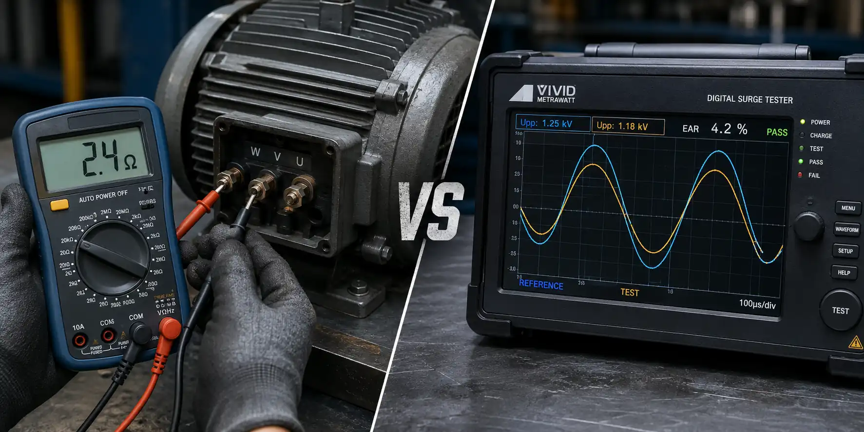
An SPD reduces the magnitude of a transient. It cannot undo damage already accumulated in turn-to-turn insulation from years of VFD reflected-wave stress, previous surge events or thermal ageing. Weakened turn insulation shows no symptom until it fails catastrophically, and a standard insulation resistance test will not detect it, because IR testing measures winding-to-earth insulation only.
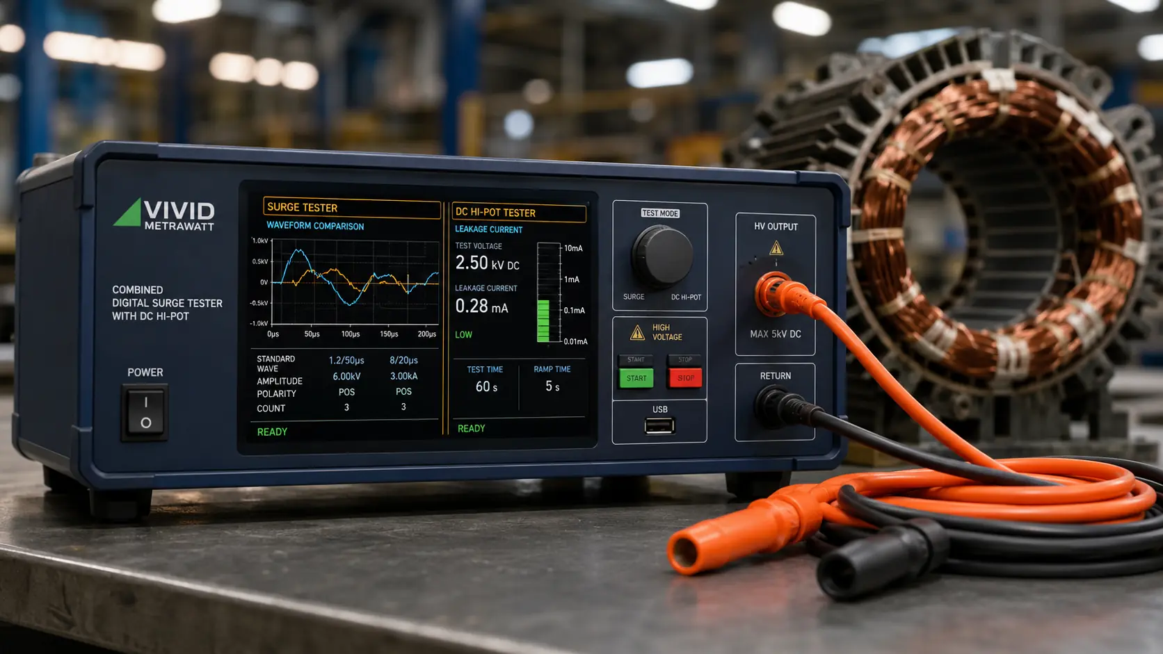
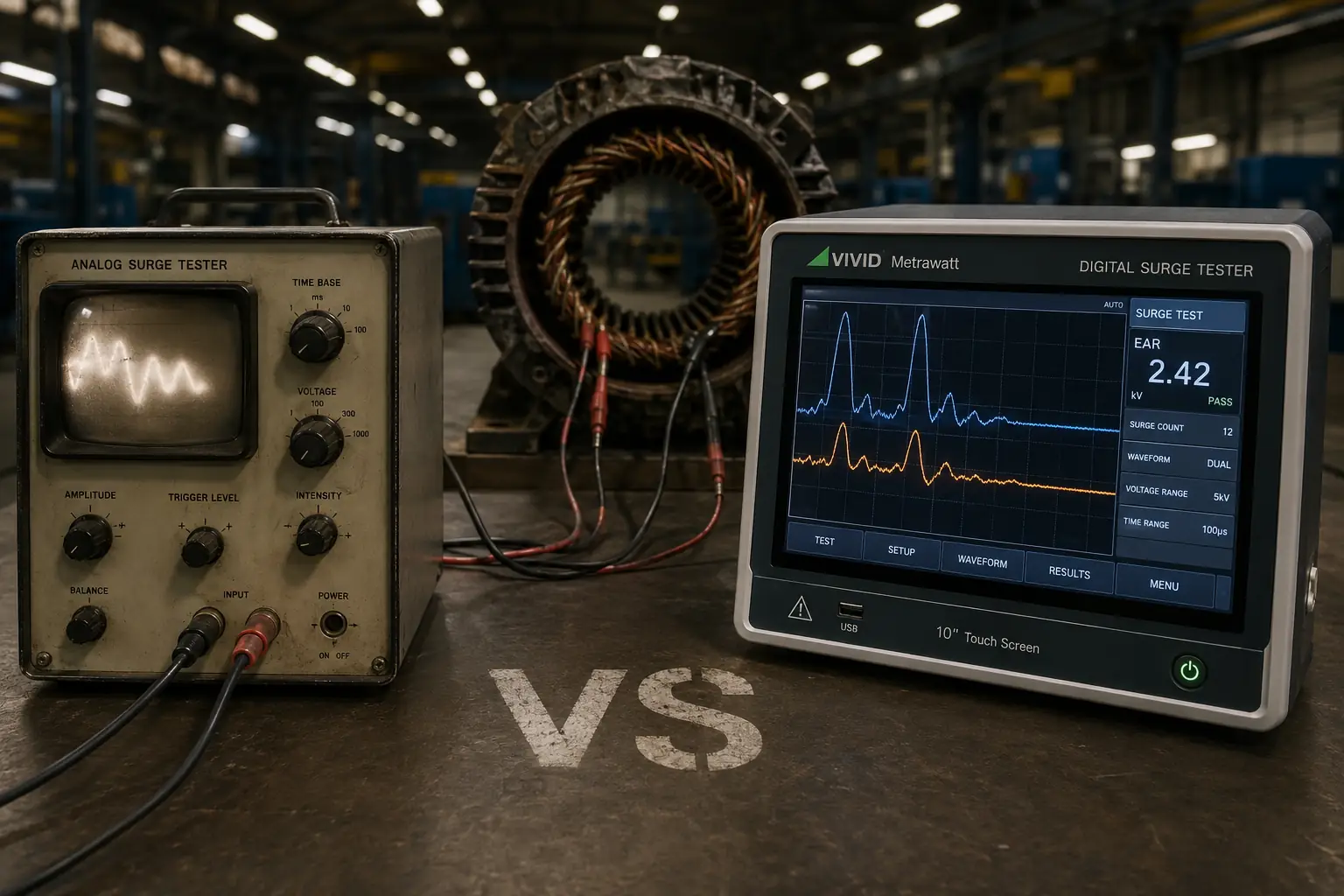
The test that does detect it is surge testing. A digital surge tester applies a controlled impulse and compares the resonant waveform between phases. A shifted first peak or altered ringing frequency reveals shorted or weakened turns long before failure.
In practice, robust plants run both:
If you are deciding what to test with, surge testing versus hi-pot testing explains which fault each method actually finds. And for the symptom-side view, early signs of motor winding failure covers what to watch for between test intervals.
Myth: “We have an SPD, so we’re protected.” An SPD degrades. Without status monitoring and periodic replacement, a plant can run for years believing it is protected while the MOV inside has already reached end of life.
Myth: “Only lightning-prone sites need SPDs.” Internal switching transients occur daily in any plant running contactors and drives, regardless of climate.
Myth: “A bigger kA rating is always better.” Oversized SPDs at the wrong stage can fail to coordinate, letting downstream devices take energy they were never rated for.
Myth: “Surge protection replaces winding testing.” Different jobs. Protection lowers exposure; testing measures condition.
Functionally they perform the same task. “Surge arrester” is conventionally used for medium- and high-voltage systems, while “surge protection device” or “SPD” is the IEC term used for low-voltage installations up to 1000 V AC.
There is no fixed lifespan — MOV-based SPDs degrade cumulatively with each surge absorbed. In a moderate industrial environment, 5–10 years is typical, but a single severe event can end a device’s life immediately. Replace based on the status indicator, not the calendar.
As close as physically possible to the equipment being protected, with total connecting lead length under 0.5 m. Type 1 goes at the service entrance, Type 2 at sub-distribution, Type 3 at the load.
Yes, in almost all cases. The manufacturer specifies a maximum backup overcurrent device to disconnect the SPD safely at end of life. Skipping it creates a fire risk.
Partially. It reduces the transient voltage reaching the motor terminals, but it cannot reverse insulation degradation already present. Pair surge protection with periodic surge testing of the windings.
Yes. VFDs generate fast-rising reflected-wave voltages at the motor terminals that standard SPDs at the panel do not address. Use dV/dt filters or motor-side terminators, and test windings more frequently.
Surge protection lowers the voltage reaching your motors. Only a surge test proves the turn-to-turn insulation survived. Our digital surge testers — from 1kV armature units to 50kV systems — are built for Indian plant conditions and backed by direct engineering support from our Mumbai facility.
Talk to Our Engineers View Surge TestersMade in India • Global supply • On-site commissioning & training